
Colorimetry calculation method and chroma calculation method for display

a colorimetry and chroma calculation technology, applied in the field of display technology, can solve the problems of second excitation problem and spectrum change of backlight, and achieve the effect of improving the accuracy of chromaticity

Active Publication Date: 2018-12-27
WUHAN CHINA STAR OPTOELECTRONICS TECH CO LTD
View PDF0 Cites 4 Cited by
  • Summary
  • Abstract
  • Description
  • Claims
  • Application Information

AI Technical Summary

Benefits of technology

The patent presents a solution for improving the accuracy of displays containing quantum dot backlight modules. It uses a reference polarizer to correct the spectrum of the backlight in response to the secondary excitation of the quantum dot film caused by the first polarizer. This accurately simulates the chromaticity offset phenomenon and provides a foundation for quantifying the design of the display. The patent also obtains a chromaticity coordinate correction factor that corrects the chromaticity due to secondary excitation of the first polarizer to improve accuracy and facilitate quantization design of the display.

Problems solved by technology

When the quantum dot backlight module is in operation, the light source emitted by the blue LED through the lower polarizer containing the APCF below the liquid crystal cell structure will be re-through the quantum dot film, which leads to the secondary excitation problem of the quantum dots, so that the spectrum of the backlight changes.
However, the panel manufacturer in the quantum dot film with color resistance design, usually need accurate spectral spectrum to carry out simulation calculations, and because the existence of secondary excitation makes the measured spectrum cannot be directly used for calculation, and the spectral variation due to the secondary excitation causes the relevant chromaticity index calculated by the backlight module to deviate from the final measured value.

Method used


Image

  • Colorimetry calculation method and chroma calculation method for display
  • Colorimetry calculation method and chroma calculation method for display
  • Colorimetry calculation method and chroma calculation method for display

Examples


Embodiment Construction

[0016]The technical solution of the present disclosure will be described in further detail below with reference to the accompanying drawings and specific embodiments in order to provide a better understanding of the technical solution of the present disclosure by those skilled in the art.

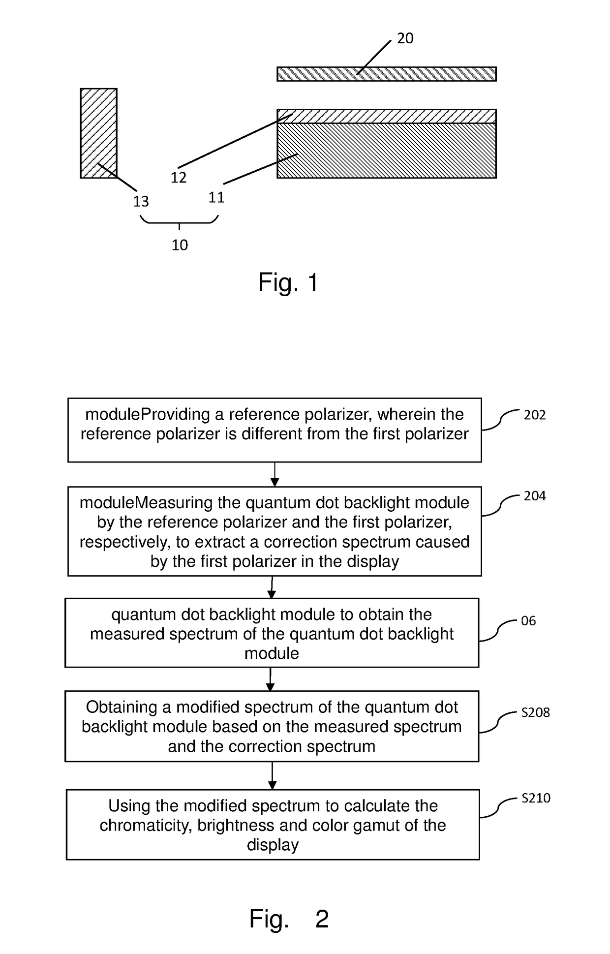
[0017]In order to provide a detailed description of the colorimetry calculation method of the display of the present disclosure, the display of the colorimetry calculation method will be described in detail. As shown in FIG. 1, FIG. 1 is a schematic structural diagram of a display used in the present disclosure. The display includes a quantum dot backlight module 10 and a first polarizer 20 arranged on the light exit side of the quantum dot backlight module 10, wherein the quantum dot backlight module 10 includes a light guide plate 11, a quantum dot thin film layer 12 arranged on the light exit side of the light guide plate 11, and a backlight 13 arranged on the light entrance side of the light gui...


PUM


Abstract

The present disclosure discloses a colorimetry calculation method for a display. The display includes a quantum dot backlight module and a first polarizer, wherein the quantum dot backlight module includes a light guide plate, a quantum dot thin film layer, and a backlight. The method obtains the correction spectrum of the quantum dot backlight module, and obtains the true spectrum of the quantum dot backlight module when the first polarizer is arranged on the light exit side of the quantum dot backlight module based on the correction spectrum and the measurement spectrum, that is, the modified spectrum, so as to accurately simulate the chromatic offset phenomenon due to the secondary excitation of the first polarizer, and provide the basis for the quantitative design of the display including the quantum dot backlight module. The present disclosure also discloses a chromaticity calculation method of a display.

Description

FIELD OF THE DISCLOSURE[0001]The present disclosure relates to a display technology field, and more particularly to a colorimetry calculation method and a chroma calculation method for a display.BACKGROUND OF THE DISCLOSURE[0002]Currently used to improve the color gamut of the small size of the display, the more promising application is using a quantum dot film (QD film) to excite the RG by the blue LED, wherein the width of the light line of the QD is about 30 nm, the narrow line width guarantees the true color of the backlight. In a backlight module containing a quantum dot film (also known as quantum dot backlight module), the blue LED is encapsulated on the light entrance side of the light guide plate, and the quantum dot film is usually placed on the light exit side of the light guide plate. When the quantum dot backlight module is in operation, the light source emitted by the blue LED through the lower polarizer containing the APCF below the liquid crystal cell structure will ...

Claims


Application Information

Patent Timeline
IPC IPC(8): G01J3/50F21V8/00G02F1/1335G02F1/13G01J3/02
CPCG01J3/506G02B6/005G02B6/0056G02F1/133528G02F1/1309G01J3/0224G02F2202/36G02F2001/133531G01M11/00G01J2003/467G02F1/133614G02F1/133531
Inventor ZHA, GUOWEI
Owner WUHAN CHINA STAR OPTOELECTRONICS TECH CO LTD
Learn More