Manual Pipe Valve Connector for Jointed Pipe Connections with Quick Release Check Valve Assembly and Uses Thereof

a technology of quick release and check valve, which is applied in the direction of drilling pipes, screw threaded joints, mechanical equipment, etc., can solve the problems of dangerous tools and techniques, high cost of systems, and other tools such as manual rig tongs, which are known to be extremely dangerous, and achieves convenient servicing and replacement of valves. , the effect of convenient and efficient makeup and breakout of connections

Active Publication Date: 2019-01-03
MCLAUGHLIN STUART
View PDF0 Cites 16 Cited by
  • Summary
  • Abstract
  • Description
  • Claims
  • Application Information

AI Technical Summary

Benefits of technology

[0024]Distinctly, the present invention allows for (1) expedient and efficient makeup and breakout of connections, (2) more secure mechanical and pressurized sealing (3) ease of servicing and replacing valves, (4) more effectual torque loading and torque distribution (5) safer pipe joint, bottom hole assembly and / or tooling accessories handling and (6) the ability to manipulate and rotate pipe in both a clockwise and counterclockwise manner for bi-directional control in freeing stuck or wedged pipe. It is for the above reasons, coupled with deficiencies of the art in the field, that inventor seeks to cure the cited insufficiencies while addressing the significant, long felt and unmet need for a useful and novel clutch connection joint assembly device and method for use.

Problems solved by technology

These systems are expensive, heavy, hydraulically actuated, laborious and cumbersome (requiring skill and training to use efficiently and safely).
Other tools such as manual rig tongs have been known to be extremely dangerous with many incidents recorded over the decades (e.g. many oilfield workers damaging or losing fingers and other body parts).
These are also very dangerous tools and techniques to implement and offer the end user little margin for error when in use.
In many of these applications the actual torque force required to secure the pipe thread connection is not recorded during thread make up and as such equipment is prone to back off and ultimately left down hole or to be retrieved (i.e. “fished out”) at a later date.
The disadvantage of the customary placement of a valve is the static nature of a valve and the relative inability to remove, service and replace the valve.
This cannot be achieved with todays threaded technology due to risk of thread back-off and separation of the tubing, drill pipe, and / or bottom hole assembly.

Method used


Image

  • Manual Pipe Valve Connector for Jointed Pipe Connections with Quick Release Check Valve Assembly and Uses Thereof
  • Manual Pipe Valve Connector for Jointed Pipe Connections with Quick Release Check Valve Assembly and Uses Thereof
  • Manual Pipe Valve Connector for Jointed Pipe Connections with Quick Release Check Valve Assembly and Uses Thereof

Examples


Embodiment Construction

[0039]Advantages of the present invention will become readily apparent to those skilled in the art from the following detailed description, wherein there is described in detail certain preferred embodiments of the present invention (and examples for illustrative purposes). Although the following detailed description contains many specific features for the purposes of illustration, one of ordinary skill in the art will appreciate that many variations and alterations to the following details are within the scope of the invention. Accordingly, the following embodiments of the invention are set forth without any loss of generality to, and without imposing limitations upon, the claimed invention. While embodiments are described in connection with the specification herein, there is no intent to limit the scope to the embodiments disclosed below. On the contrary, the intent is to cover all alternatives, modifications, and equivalents.

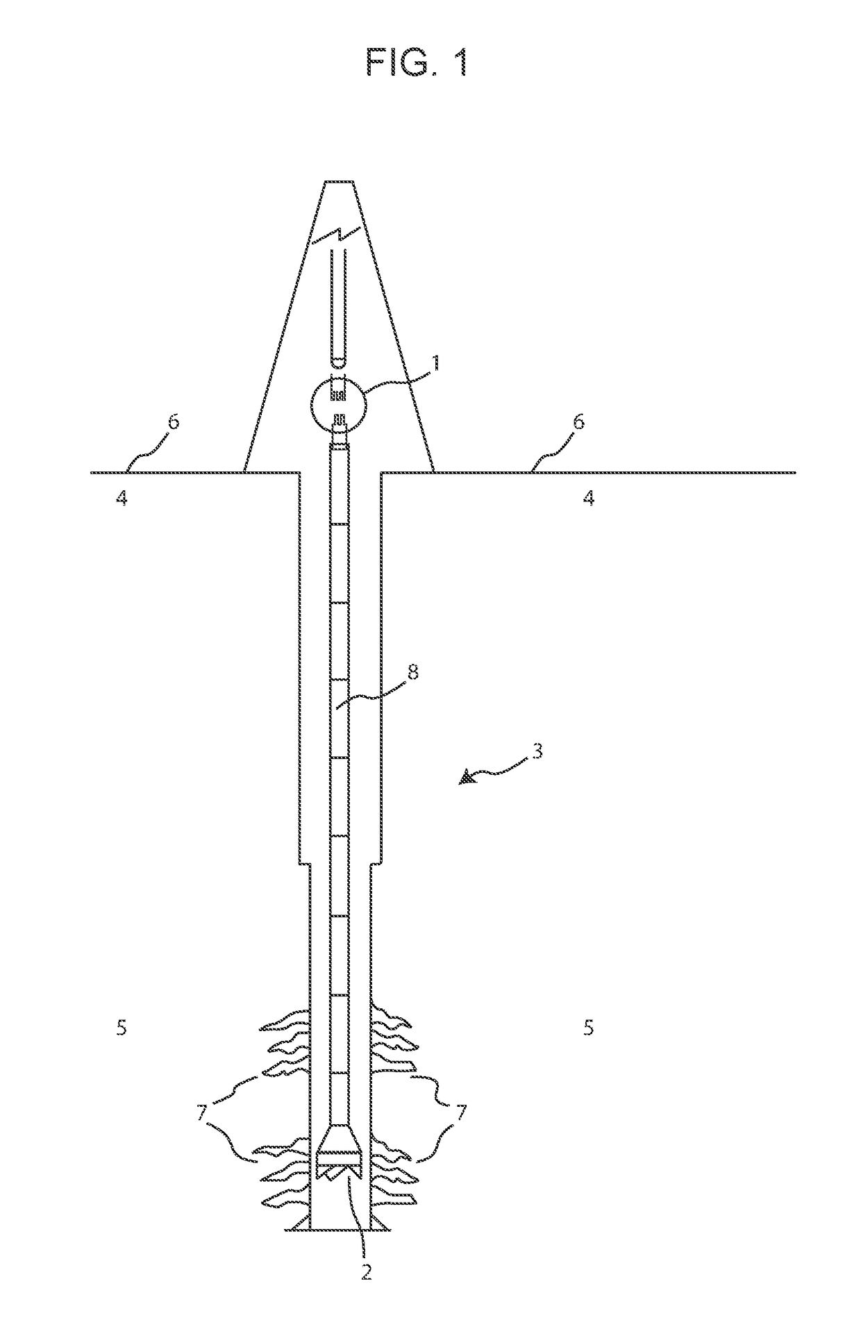
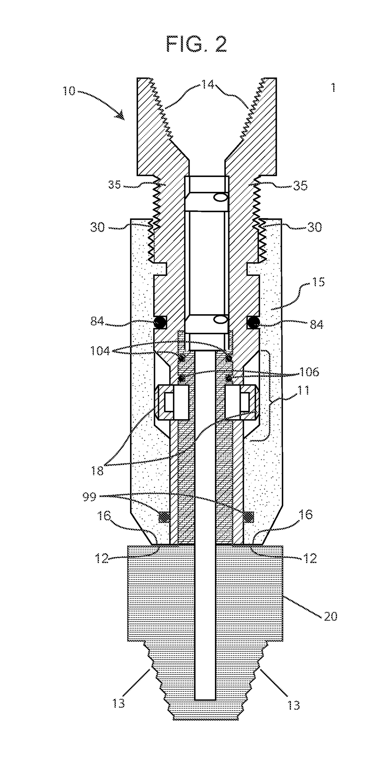
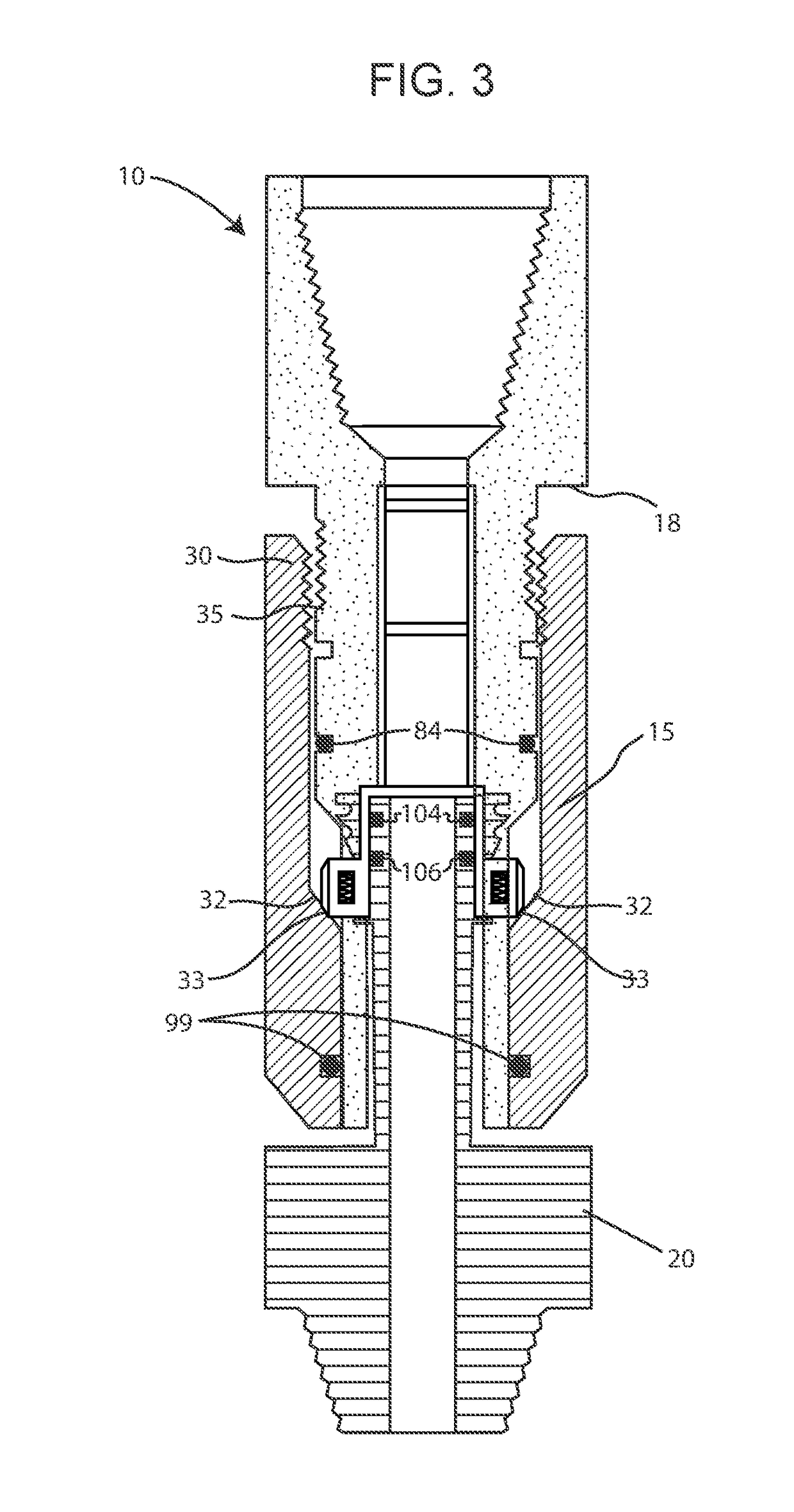
[0040]FIG. 1 illustrates the present invention that is t...


PUM


Abstract

The present invention provides a novel clutch connector assembly for jointed pipe, threaded pipe, coiled tubing or any threaded or non-threaded pipe for a bottom hole assembly that eliminates the need to use screw threads to mate two pipes or mechanical assemblies, harbors a spring-loaded mechanical locking system in addition in to a pressure-activated, component protectant system, requires no significant tools, other than an Allen wrench or similar screw setting device, permits distributed torque loading, allows for movement in either a clockwise or counter clockwise rotational direction through interlocking castellations and presents a removeable and replaceable valve assembly preventing retrograde hydrocarbon advancement through a drilling pipe.

Description

CROSS-REFERENCE TO RELATED APPLICATIONS[0001]Priority claimed to Non-Provisional U.S. Ser. No. 15 / 330,946 filed Feb. 3, 2015CROSS REFERENCE TO RELATED APPLICATIONS[0002]The present application is a Continuation-in-Part application (CIP) of previously filed U.S. patent application Ser. No. 15 / 330,946 filed Feb. 3, 2015 the entire contents of which are incorporated by reference in their entirety.FEDERALLY SPONSORED RESEARCH OR DEVELOPMENT[0003]Not ApplicableINCORPORATION BY REFERENCE OF MATERIAL SUBMITTED ON A COMPACT DISK[0004]Not ApplicableFIELD OF THE INVENTION[0005]The present invention relates generally to the design of a mechanical connection assembly used in conjunction with jointed pipe, threaded pipe, coiled tubing, stick pipe and any other threaded or non-threaded pipe section (or tubular) for down hole operations that involve and utilize inline safety valves (also known in the art as check valves, safety valves, flapper valves and ball valves or valves of similar nature) th...

Claims


Application Information

Patent Timeline
Patent Type & Authority Applications(United States)
IPC IPC(8): E21B17/043F16L19/00F16L15/08
CPCE21B17/043F16L19/005F16L15/08E21B2034/005E21B17/04E21B17/046E21B2200/05
Inventor MCLAUGHLIN, STUART
Owner MCLAUGHLIN STUART
Why Eureka
Try Eureka