Optical film, polarizing plate, image display device, method for producing optical film, and method for producing polarizing plate

a technology of polarizing plate and optical film, which is applied in the direction of polarizing elements, instruments, other domestic articles, etc., can solve the problems of cycloolefin-based polymers not being easily closely attached deterioration of adhesiveness to liquid crystal layers, etc., and achieves the effect of ensuring adhesiveness and without deterioration

Active Publication Date: 2019-01-03
FUJIFILM CORP
View PDF4 Cites 1 Cited by
  • Summary
  • Abstract
  • Description
  • Claims
  • Application Information

AI Technical Summary

Benefits of technology

[0085]According to the present invention, it is possible to provide an optical film capable of ensuring adhesiveness between a polymer film and a liquid crystal layer without deteriorating the alignment of a liquid crystal compound even in a case where the liquid crystal layer is provided adjacent to the polymer film formed by using a cycloolefin-based polymer, a polarizing plate using the same, an image display device, a method for producing an optical film, and a method for producing a polarizing plate.

Problems solved by technology

However, there is concern that adhesiveness to the liquid crystal layer and the alignment of the liquid crystal compound is deteriorated by removing the alignment layer.
However, there is concern that the cycloolefin-based polymer is not easily closely attached to a liquid crystal layer compared to a cellulose-based polymer which has been conventionally used.

Method used


Image

  • Optical film, polarizing plate, image display device, method for producing optical film, and method for producing polarizing plate
  • Optical film, polarizing plate, image display device, method for producing optical film, and method for producing polarizing plate
  • Optical film, polarizing plate, image display device, method for producing optical film, and method for producing polarizing plate

Examples


example 1

[0316]

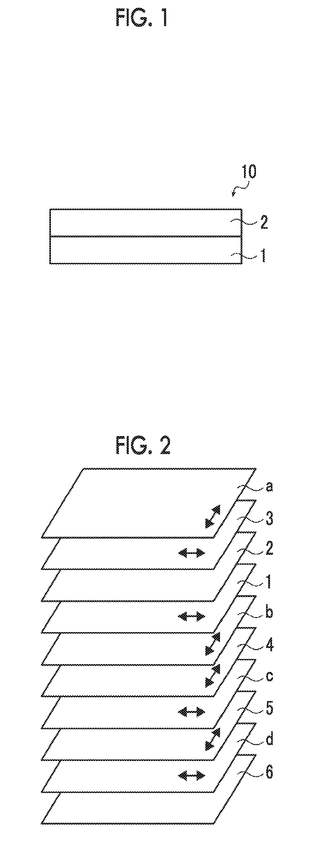
[0317]One surface of a cycloolefin polymer film (trade name: ARTON FILM, Re=95 nm, Rth=100 nm, film thickness 20 μm, manufactured by JSR Corporation) was subjected to a corona treatment in a discharge amount of 125 W·min / m2 and a liquid crystal layer forming composition 1 prepared with the following composition was applied to the corona-treated surface using a #3.0 wire bar.

[0318]Next, the solvent of the composition was dried and heated with hot air at 70° C. for 90 seconds to mature the alignment of the liquid crystal compound.

[0319]Next, irradiation with ultraviolet rays (300 mJ / cm2) was performed at 40° C. in an oxygen concentration of 0.1% under nitrogen purge and the alignment of the liquid crystal compound was fixed. Thus, an optical film of Example 1 was prepared.

Liquid Crystal Layer Forming Composition 1Liquid crystal compound R1 below100.0parts by massAlignment assistant (A1) below1.0part by massCompound B1 represented by Formula (I) below1.0part by massPolymerization...

examples 2 to 17

, Comparative Examples 1 to 4, and Comparative Examples 6 to 9

[0342]Optical films of Examples 2 to 17 and Comparative Examples 1 to 4 and 6 to 9 were prepared and evaluated in the same manner as in Example 1 except that the kind of the polymer film, the film thickness, Re(550), Rth(550), the kind of the liquid crystal compound, the kind and the added amount of the compound represented by Formula (I) above, and the thickness of the liquid crystal layer were changed to values shown in Table 1 above. The results are shown in Table 1 above.

[0343]In Table 1 above, in Examples 16 and 17, a discotic liquid crystal compound was used. Since the phase difference was different from the phase differences in other examples, the alignment was evaluated based on the value of Re(550) with respect to a film thickness of 1 μm of the liquid crystal layer instead of the value of |Rth(550)| with respect to a film thickness of 1 μm of the liquid crystal layer. The evaluation was performed based on the sa...

example 18

[0352]An optical film of Example 18 was prepared in the same manner as in Example 1 except that in the liquid crystal composition, instead of using 250.0 parts by mass of methyl acetate, 250.0 parts by mass of acetone was used, and the thickness of the polymer film, Re(550), Rth(550), the kind of the liquid crystal compound, the kind and the added amount of the compound represented by Formula (I) above, and the thickness of the liquid crystal layer were changed to values shown in Table 1 above. The results are shown in Table 1 above.


PUM

PropertyMeasurementUnit
thickness direction retardation Rth1aaaaaaaaaa
thickness direction retardation Rth2aaaaaaaaaa
thickness direction retardation Rth3aaaaaaaaaa

Abstract

The present invention relates to an optical film which ensures adhesiveness between a polymer film and a liquid crystal layer without deteriorating the alignment of a liquid crystal compound; a polarizing plate using the same; an image display device; a method for producing an optical film; and a method for producing a polarizing plate. The optical film includes a polymer film including a cycloolefin-based polymer, and a liquid crystal layer that is provided adjacent to the polymer film, in which the liquid crystal layer is formed by using a liquid crystal composition containing a liquid crystal compound and a compound having a specific structure, where the liquid crystal composition contains the compound having a specific structure at a content of 0.5% to 7.0% by mass with respect to a mass of the liquid crystal compound, and a predetermined eccentricity value is 20% to 80%.

Description

CROSS-REFERENCE TO RELATED APPLICATIONS[0001]This application is a Continuation of PCT International Application No. PCT / JP2017 / 010136 filed on Mar. 14, 2017, which claims priority under 35 U.S.C. § 119(a) to Japanese Patent Application No. 2016-057566 filed on Mar. 22, 2016, Japanese Patent Application No. 2016-097941 filed on May 16, 2016, Japanese Patent Application No. 2016-225802 filed on Nov. 21, 2016, Japanese Patent Application No. 2016-256220 filed on Dec. 28, 2016 and Japanese Patent Application No. 2017-011673 filed on Jan. 25, 2017. Each of the above applications is hereby expressly incorporated by reference, in its entirety, into the present application.BACKGROUND OF THE INVENTION1. Field of the Invention[0002]The present invention relates to an optical film, a polarizing plate, an image display device, a method for producing an optical film, and a method for producing a polarizing plate.2. Description of the Related Art[0003]Conventionally, a film having a phase differ...

Claims


Application Information

Patent Timeline
Patent Type & Authority Applications(United States)
IPC IPC(8): G02B5/30G02F1/1335C08L65/00C08G61/08B32B27/08B32B7/12
CPCG02B5/305G02F1/133528G02B5/3016C08L65/00C08G61/08B32B27/08B32B7/12C08L2203/20C08G2261/418B32B2457/202C08G2261/724C08F222/1025H10K50/86C08F230/06B32B27/325G02B5/30G02F1/1335H05B33/02B32B2307/418B32B2307/42B32B2305/55B32B2457/20H10K50/00B32B7/023C08L45/00C09K2323/00C08F222/102
Inventor IIJIMA, KOJIIWASAKI, TATSUYAOHMURO, KATSUFUMISUZUKI, MASAAKI
Owner FUJIFILM CORP
Why Eureka
Try Eureka