
Eureka
For R&D, Eureka makes reading and utilizing patents & technical documents easy.
Eureka AIR
Designed for self-driven R&D workflows. Generate viable solutions, solve complex R&D challenges, empower your innovation with AI.

Eureka Materials
Designed for material experts only. Revolutionize your material R&D, from search, analyze, to developing new materials.

TechResearch
Generate reliable direction feasibility study reports for your R&D in just a few steps.

TechSeek
Discover and master advanced knowledge NOW. Basics, ideas, possibilities, all at once.

TechMind
As an expert in R&D Theories, TechMind can generates customized viable solutions instantly.

TechRisk
Analyze your overall solution with one click, know your potential R&D risks in advance.

TechMonitor
Get weekly tech updates, stay abreast of the latest tech innovations and key insights.
Program generation method and electronic control unit
- Summary
- Abstract
- Description
- Claims
- Application Information
AI Technical Summary
Benefits of technology
Problems solved by technology
Method used
Image

Examples
first embodiment
[0049]1. A Program Generation Method and a Program Generated by Such Method (i.e., Subject Program)
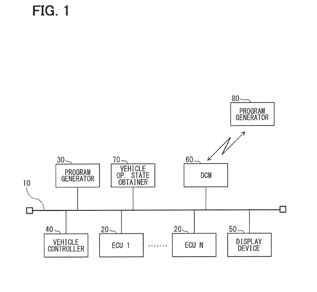
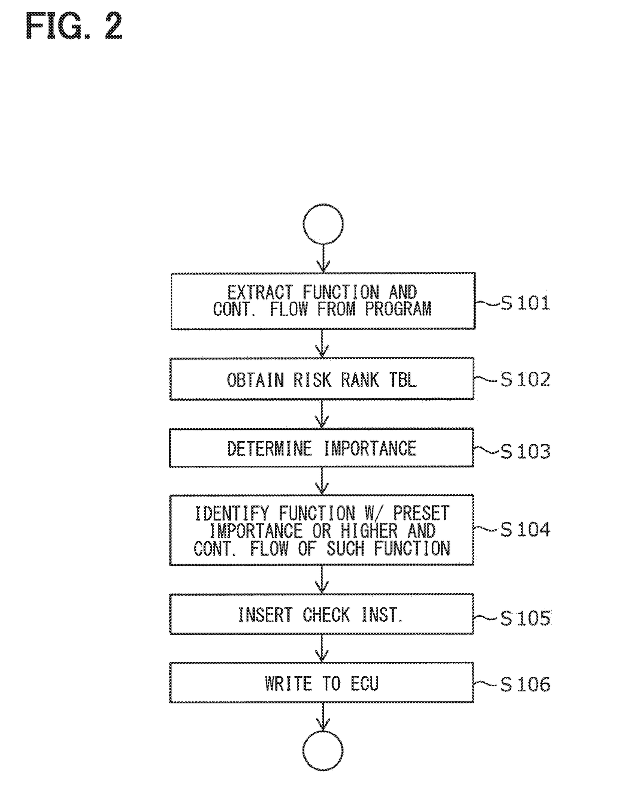
[0050]FIG. 2 is a flowchart of a program generation method described in the present embodiment. Each step of the flowchart describing a flow of control as a whole is described with reference to FIGS. 3 to 6. Note that the program generation method is performed by the program generator 30 or the program generator 80, which may be a general-purpose device or a dedicated, specific device having a processor (e.g., CPU) and a memory. The program generation method may also be performed by or within the electronic control unit (ECU) 20, or like devices, to which the generated program is written.
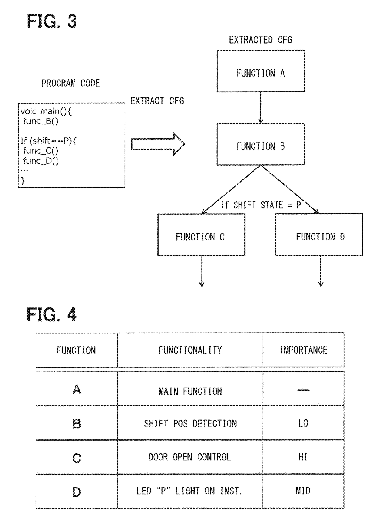
[0051]First, a “function” used in a “program code” of a program that is written to the electronic control unit 20 and a control flow representing a call / return relationship of the “function” are extracted. The program described above may be, for example, a control, or a control logic, for (i) detection...
second embodiment
[0093]According to the first embodiment, the check instruction that checks the control flow involving the identified function is inserted, and, once inserted, the check instruction itself may be configured to always perform a check process.
[0094]On the other hand, in the present embodiment, the check instruction does not always perform a check process, but the check instruction is configured to selectively perform the check process during the execution of the subject program.
[0095]1. A Program Generation Method and a Generated Program by Such Method (i.e., Subject Program)
[0096]The program generation method in the present embodiment is fundamentally the same as the first embodiment described with reference to FIG. 2. However, in the present embodiment, the predetermined importance specified at S104 is set to be lower than the one in the first embodiment. For example, the function having LO importance or higher than LO is identified, and the control flow involving the function(s) for...
third embodiment
[0109]According to the second embodiment, the importance of the function in the program code is fixed, and, based on the determination of the importance to be checked, which is made based the information input from the external device, the check instruction is selectively performed with reference to the importance of the function. On the other hand, in the present embodiment, the importance of the function in the program code is changed according to a situation.
[0110]1. A Program Generation Method and a Generated Program by Such Method (i.e., Subject Program)
[0111]The program generation method of the present embodiment is fundamentally the same as the first embodiment and as the second embodiment described with reference to FIG. 2. However, how the risk rank table is obtained at S102 and the check instruction of S105 are respectively different therefrom.
[0112]FIG. 13 shows a risk rank table used in the present embodiment.
[0113]The risk rank table of the present embodiment shows that...
PUM
 Abstract
Description
Claims
Application Information
 - R&D Engineer
- R&D Manager
- IP Professional
- Industry Leading Data Capabilities
- Powerful AI technology
- Patent DNA Extraction
Browse by: Latest US Patents, China's latest patents, Technical Efficacy Thesaurus, Application Domain, Technology Topic, Popular Technical Reports.
© 2024 PatSnap. All rights reserved.Legal|Privacy policy|Modern Slavery Act Transparency Statement|Sitemap|About US| Contact US: help@patsnap.com