Carbon nanotube bonded sheet and method for producing carbon nanotube bonded sheet

a carbon nanotube and bonded sheet technology, applied in the field of a method for producing carbon nanotube bonded sheet, can solve the problems of difficult to secure the thermal conductivity of the tim, limit the improvement of thermal conductivity, etc., and achieve the effect of reducing the drop of cnt and producing efficiently

Inactive Publication Date: 2019-01-10
HITACHI ZOSEN CORP
View PDF4 Cites 5 Cited by
  • Summary
  • Abstract
  • Description
  • Claims
  • Application Information

AI Technical Summary

Benefits of technology

[0031]The carbon nanotube bonded sheet of the present invention can conform to subtle dents and bumps on the surface of an object and suppress dropping of the CNT.
[0032]With the method for producing a carbon nanotube bonded sheet of the present invention, the above-described carbon nanotube bonded sheet can be produced efficiently with an easy method.

Problems solved by technology

However, the polymer sheet cannot sufficiently conform to subtle bumps and dents (surface roughness) on the surfaces of the electronic component and heat sink, and the subtle bumps and dents may cause gaps between the electronic component and the heat sink, and there are limitations as to improvement in thermal conductivity.
The silicone grease can conform to the subtle bumps and dents on the surfaces of the electronic component and heat sink, but repetitive changes in temperature may cause pumping out (discharge from between the electronic component and heat sink), and it is difficult to secure the thermal conductivity of the TIM for a long period of time.

Method used


Image

  • Carbon nanotube bonded sheet and method for producing carbon nanotube bonded sheet
  • Carbon nanotube bonded sheet and method for producing carbon nanotube bonded sheet
  • Carbon nanotube bonded sheet and method for producing carbon nanotube bonded sheet

Examples


first embodiment

1. First Embodiment

(1) Configuration of Thermal Conductive Sheet

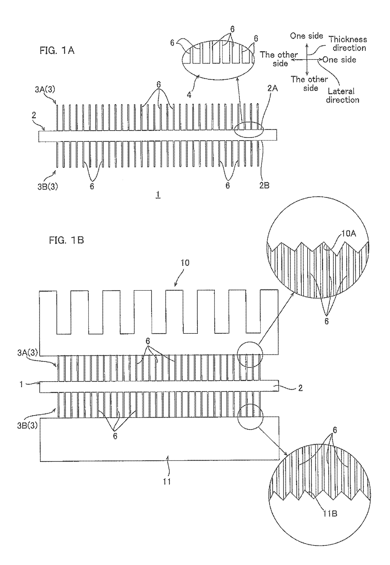
[0042]The thermal conductive sheet 1 (en example of CNT bonded sheet) includes, as shown in FIG. 1A, a fixture sheet 2, and two carbon nanotube array sheets 3 (hereinafter referred to as CNT array sheet 3).

[0043]The fixture sheet 2 has a sheet shape (flat plate shape), to be specific, the fixture sheet 2 has a predetermined thickness, extends in a surface direction orthogonal to its thickness direction (vertical direction and lateral direction), and has a flat front face 2A (one side in thickness direction) and a flat back face 2B (the other side in thickness direction).

[0044]The fixture sheet 2 has a thickness of, for example, 10 μm or more, preferably 50 μm or more, and for example, 500 μm or less, preferably 300 μm or less.

[0045]The fixture sheet 2 is formed from a sintered body of an inorganic material. To be specific, the fixture sheet 2 is a ceramic sheet formed by bonding of the inorganic material particles by si...

second embodiment

2. Second Embodiment

[0150]In the first embodiment, as shown in FIG. 4C, the fixture sheet 2 formed from the sintered body 4 of the inorganic material is prepared, and the CNT array sheet 3 is disposed on the fixture sheet 2, and thereafter calcined to produce the thermal conductive sheet 1. However, the present invention is not limited to such a method for producing the thermal conductive sheet.

[0151]In the second embodiment, as shown in FIG. 5A, a resin sheet 7 containing the inorganic particles 8 is prepared, and a CNT array sheet 3 is disposed on the resin sheet 7, and thereafter they are calcined to produce a thermal conductive sheet 1. In the second embodiment, the same reference numerals are given to those members that are the same as those in the above-described first embodiment, and description thereof is omitted.

[0152]To be more specific, as shown in FIG. 5A, first, the resin sheet 7 containing the inorganic particles 8 is prepared.

[0153]The resin sheet 7 has a sheet shape ...

third embodiment

3. Third Embodiment

[0171]Next, description is given as to the third embodiment with reference to FIG. 5B and FIG. 5C. The same members as those in the above-described first embodiment and second embodiment are given the same reference numerals, and description thereof is omitted.

[0172]In the above-described second embodiment, the resin sheet 7 containing the inorganic particles 8 is prepared, and the CNT array sheet 3 is disposed on both sides of the resin sheet 7, and thereafter the resin sheet 7 is heated to sinter the inorganic particles 8 to produce the thermal conductive sheet 1. However, the present invention is not limited to such a method for producing the thermal conductive sheet.

[0173]In the third embodiment, first, as shown in FIG. 5B, a paste containing the inorganic particles 8 is prepared (paste preparation step).

[0174]To be specific, the paste contains the above-described resin material and inorganic particles 8. To prepare such a paste, the inorganic particles 8 are ...


PUM

PropertyMeasurementUnit
densityaaaaaaaaaa
thicknessaaaaaaaaaa
thicknessaaaaaaaaaa

Abstract

A carbon nanotube bonded sheet includes a fixture sheet formed from a sintered body of an inorganic material, and a carbon nanotube array sheet bonded to the sintered inorganic material of the fixture sheet.

Description

TECHNICAL FIELD[0001]The present invention relates to a carbon nanotube bonded sheet and a method for producing a carbon nanotube bonded sheet.BACKGROUND ART[0002]There has been known that a thermal conductive material (Thermal Interface Material: hereinafter referred to as TIM) is disposed between an electronic component and a heat sink to reduce the gap between the electronic component and the heat sink to efficiently conduct heat generated from the electronic component to the heat sink. For such a TIM, a polymer sheet composed of a polymer material and a silicone grease has been known.[0003]However, the polymer sheet cannot sufficiently conform to subtle bumps and dents (surface roughness) on the surfaces of the electronic component and heat sink, and the subtle bumps and dents may cause gaps between the electronic component and the heat sink, and there are limitations as to improvement in thermal conductivity.[0004]The silicone grease can conform to the subtle bumps and dents on...

Claims


Application Information

Patent Timeline
Patent Type & Authority Applications(United States)
IPC IPC(8): C09K5/14C23C16/26B22F7/08B28B11/24C01B32/168H01L23/00
CPCC09K5/14H01L2924/01014B22F7/08B28B11/243C01B32/168H01L24/29H01L24/27B82Y30/00B82Y40/00C01B2202/24H01L2224/29193H01L2224/27505H01L2224/27003H01L2224/29166H01L2224/29138C23C16/26H01L23/373B32B9/007B32B15/04B32B38/0036H05K7/20H01L23/36B32B2305/80B32B9/00B32B5/02
Inventor INOUE, TETSUYAMARUYAMA, HIROYUKI
Owner HITACHI ZOSEN CORP
Why Eureka
Try Eureka