Self-restraining abrasion prevention exhaust conduit

a technology of exhaust conduits and self-restraining abrasion, which is applied in the direction of hoses, mechanical devices, adjustable joints, etc., can solve the problems of external corrugated bellows, severe abrasion between damping elements, and failure of components

Active Publication Date: 2019-01-10
AMERICAN BOA
View PDF1 Cites 3 Cited by
  • Summary
  • Abstract
  • Description
  • Claims
  • Application Information

AI Technical Summary

Benefits of technology

[0010]It is a further objective of the invention to provide a multiple component hot gas hose having an exterior bellows and a liner such as a metallic interlock structure together with intermediate components preventing the bellows from going into natural frequency resonance as well as preventing bellows-to-liner interaction or contact at any operating angle or displacement.

Problems solved by technology

For example, engagement between the intermediate damping elements and the interlock liner or engagement between the intermediate damping elements and the external corrugated bellows results in abrasion of the interlock liner or of the damping element or of the external corrugated bellows, leading to failure of components.
Nevertheless, prior damping elements are primarily disposed between liner and bellows for damping natural frequencies of the bellows and not, if at all, for any component interaction or abrasion preventing function.
Without assembly pretension, later interaction between components accelerates when there is high g-loading, causing severe abrasion between the damping element and the interlock liner or the damping element and the external corrugated bellows.
Moreover, assembly pretension or interference fit of components is not feasible without use of some sort of a guiding element to permit assembly of bellows and interlock liner with intermediate dampers.
And some prior, multiple component, hot gas hoses are only able to accommodate maximum frequency and amplitudes at certain angles or operational displacements due to bellows' natural frequencies and bellows-to-interlock liner interactions.
If bellows and interlock liner do interact, either can cause a failure by means of leaking, thus no longer being emission compliant.
While one solution might be provision of a larger design gap between the bellows and the interlock liner, that results in either a smaller interlock internal diameter and a decreased gas flow with exhaust restrictions, or a larger outside bellows diameter which is often not possible due to overall packaging constraints from surrounding components.

Method used


Image

  • Self-restraining abrasion prevention exhaust conduit
  • Self-restraining abrasion prevention exhaust conduit
  • Self-restraining abrasion prevention exhaust conduit

Examples


Embodiment Construction

[0066]Turning now to the drawings, it will be appreciated that many variations and embodiments of the components described are within the contemplation of the invention. For example, the drawings described above are illustrative of a variety of component structures and numbers thereof. Thus, it will be appreciated that variations and embodiments are described without limitation to other elements and features as will be appreciated. Without limitation, configuration of the damper cushions, elastic spacers, liners, bellows, over mesh or braids or other features may vary. Also, components of the invention with similarities to others in alternate embodiments bear the same identifying numbers.

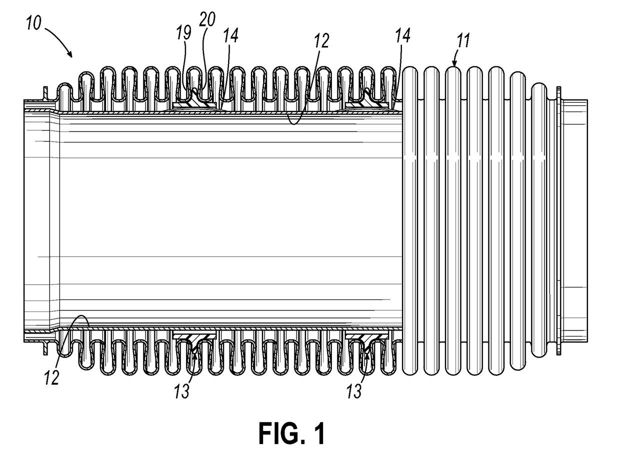
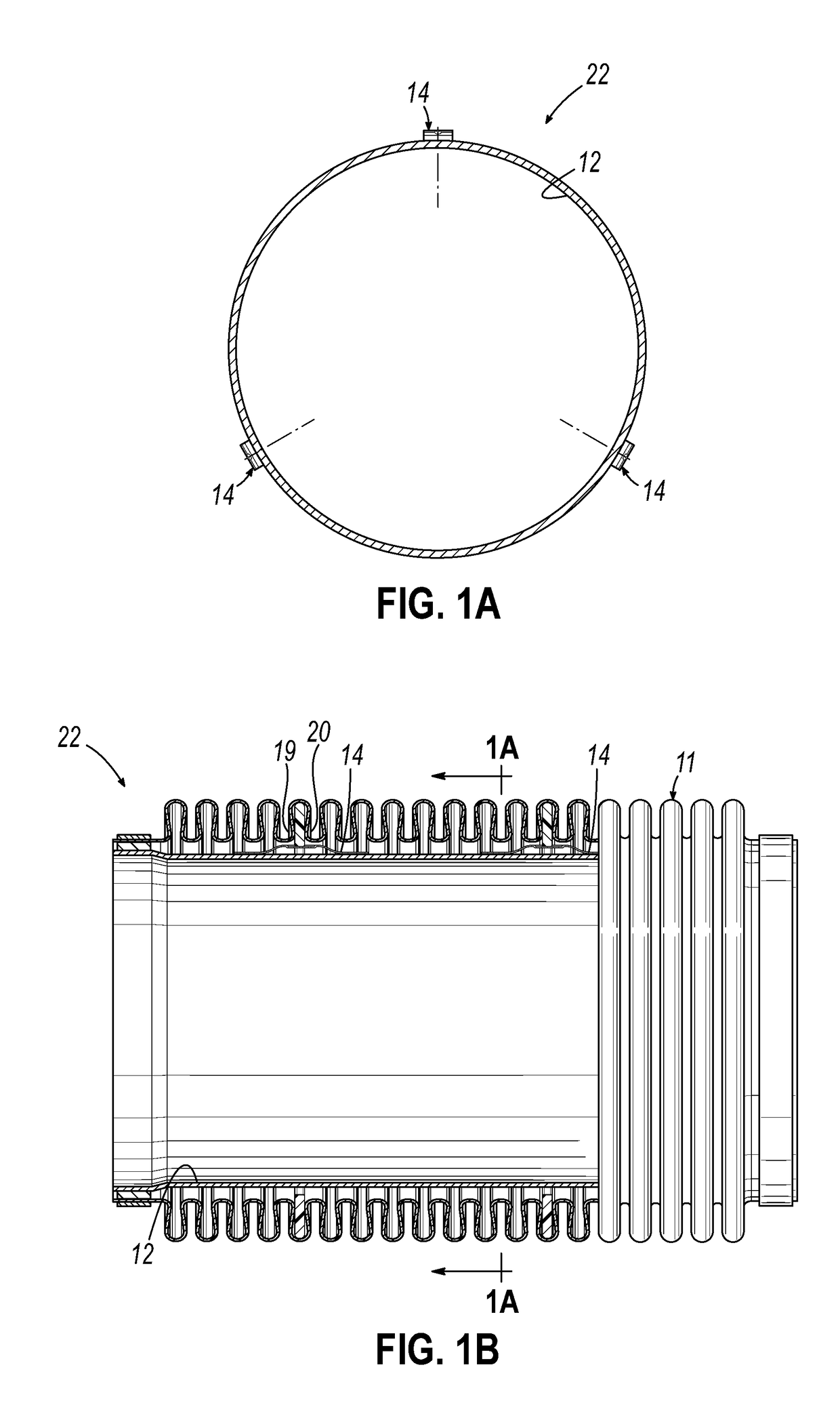
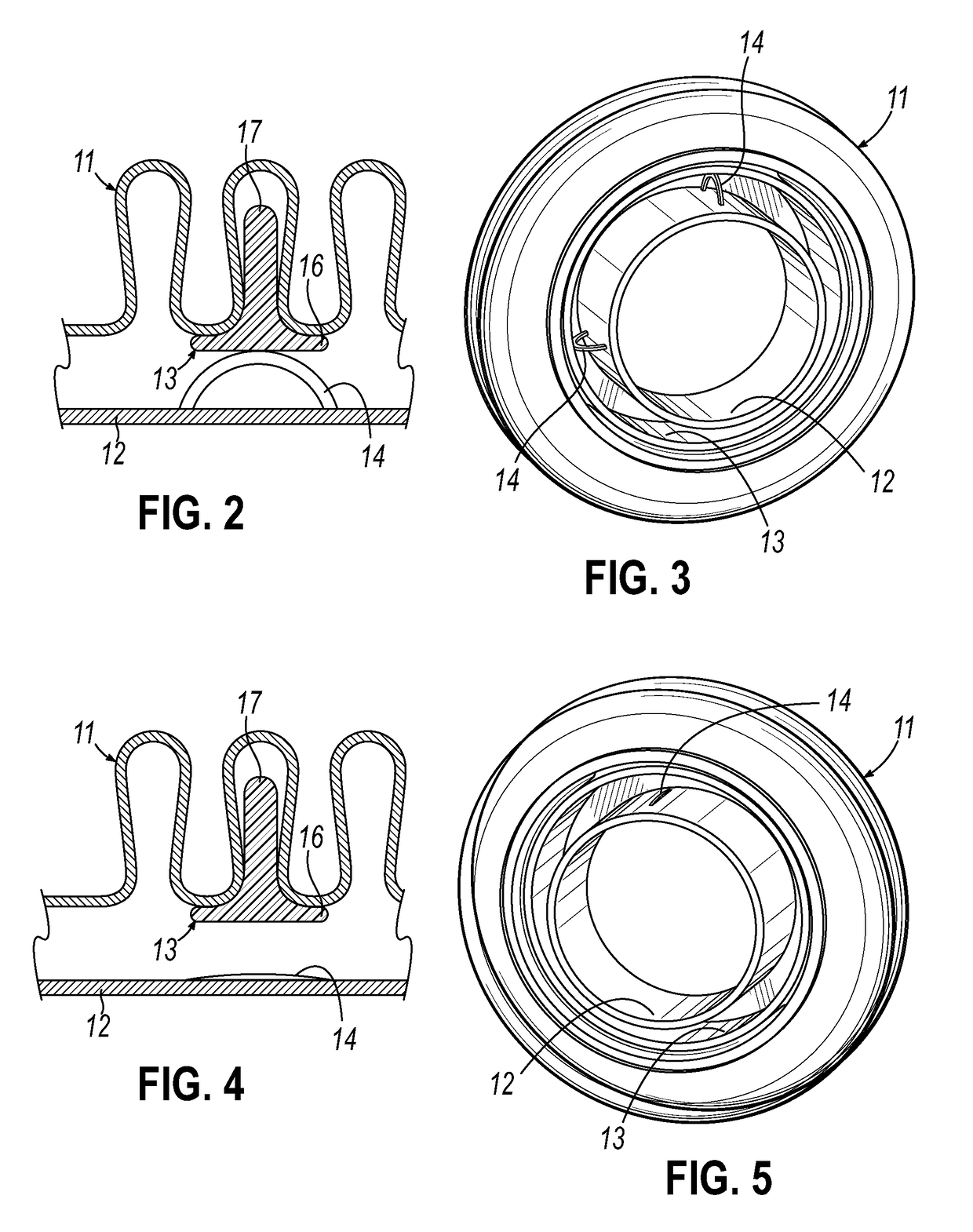
[0067]A preferred multiple component conduit 10 in FIG. 1 includes a flexible bellows member 11, a damper 13, an expandable interlock liner 12 and a plurality of metallic, elastic spacers 14 secured at ends to liner 12. Liner 12 may be of any suitable configuration, such as a metallic interlock stru...


PUM


Abstract

A multiple component hot gas flowing conduit has an elongated, convoluted bellows, an interlock liner, frequency dampers and elastic spacers engaging the dampers and biasing the dampers into respective bellows convolution with no contact of bellows and liner for all operating states of the conduit. Assembly pretension of the interlock liner preferably flattens out the elastic spacers permitting assembly of the liner into the bellows and upon relaxation of the liner, the spacers extend radially outwardly to engage and bias the dampers into the bellows. The bellows is convoluted throughout, or may have convoluted ends with an integral smooth-wall tube therebetween. Components are isolated from abrasion against one another.

Description

PRIORITY CLAIM[0001]Applicant claims benefit of the filing date of Jul. 6, 2017 which is the filing date of U.S. Provisional Patent Application Ser. No. 62 / 529,066 which application is incorporated herein in its entirety as if fully set forth herein.FIELD OF THE INVENTION[0002]This invention relates to multiple component conduits for hot exhaust gases and more particularly to conduits, hoses, decoupling elements and the like including corrugated exterior bellows, internal metallic liner hose and intermediate damping elements disposed therebetween.BACKGROUND OF THE INVENTION[0003]Hot exhaust gas flowing hoses having an external corrugated bellows sleeve, internal hoses of metallic interlock or other forms of liners, and / or damper elements therebetween are known. Such devices, for example, are disclosed in U.S. Pat. Nos. 8,453,680; 6,230,748 and U.S. Pat. No. 9,970,578, all of which are expressly incorporated herein by reference as if fully expressly set forth herein.[0004]There are s...

Claims


Application Information

Patent Timeline
Patent Type & Authority Applications(United States)
IPC IPC(8): F01N13/18F16L27/11F16L51/02F16L27/10F16L55/033
CPCF01N13/1816F16L27/11F01N2470/12F16L27/1004F16L55/033F16L51/025F16L27/111F16L51/026
Inventor GADE, SRINIVASDICKMAN, ERICK MICHAEL
Owner AMERICAN BOA
Why Eureka
Try Eureka