Selective color display of a thermal image

a thermal image and color display technology, applied in image enhancement, color signal processing circuits, instruments, etc., can solve the problems of long time-consuming and laborious production of thermal imaging sensors, limiting the use of high-performance, long-wave imaging to high-value instruments, such as aerospace, military, or large-scale commercial applications

Active Publication Date: 2019-01-10
SEEK THERMAL
View PDF0 Cites 11 Cited by
  • Summary
  • Abstract
  • Description
  • Claims
  • Application Information

AI Technical Summary

Benefits of technology

[0018]In another embodiment of the second aspect the one or more threshold criteria may be set to be at least one of greater than all values in the background scene, less than all values in the background scene, equal to specified values in the background scene or in between ranges of values in the background scene.
[0019]In another embodiment of the second aspect the one or more threshold criteria may be set to be pixels one of above or below all values in the threshold scene.

Problems solved by technology

Such thermal imaging sensors have long been expensive and difficult to produce, thus limiting the employment of high-performance, long-wave imaging to high-value instruments, such as aerospace, military, or large-scale commercial applications.

Method used


Image

  • Selective color display of a thermal image
  • Selective color display of a thermal image
  • Selective color display of a thermal image

Examples


example imaging

Systems

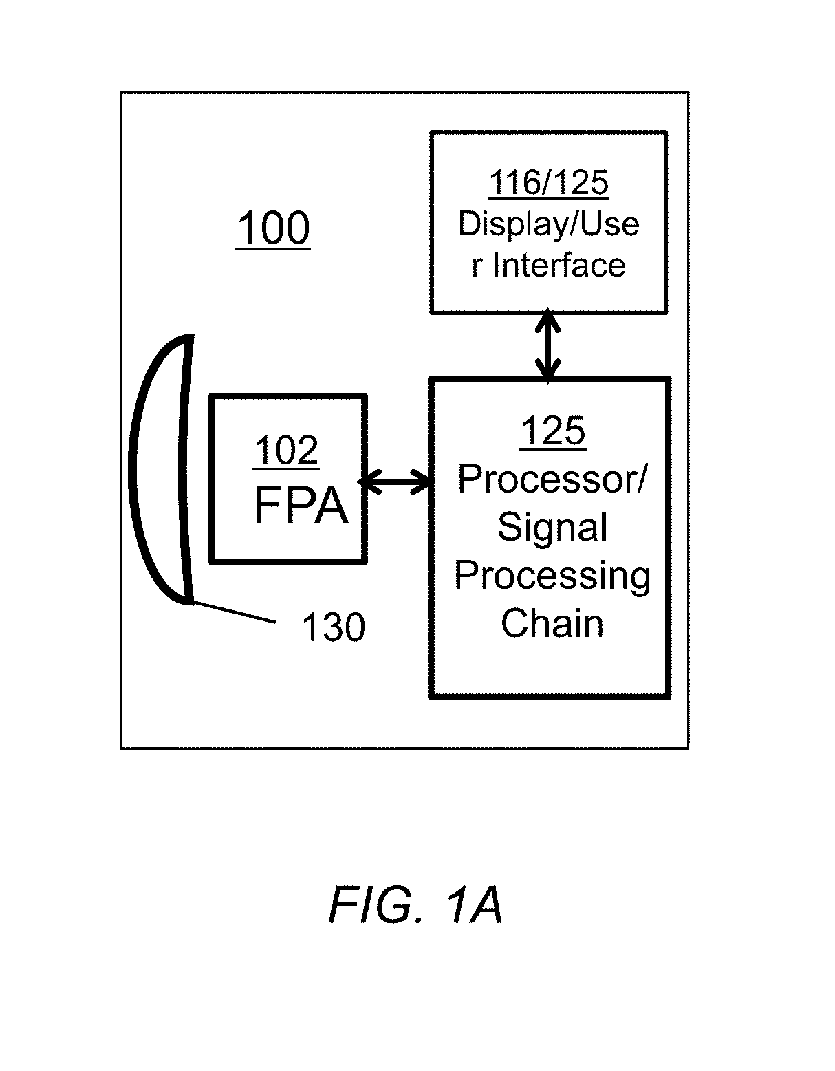
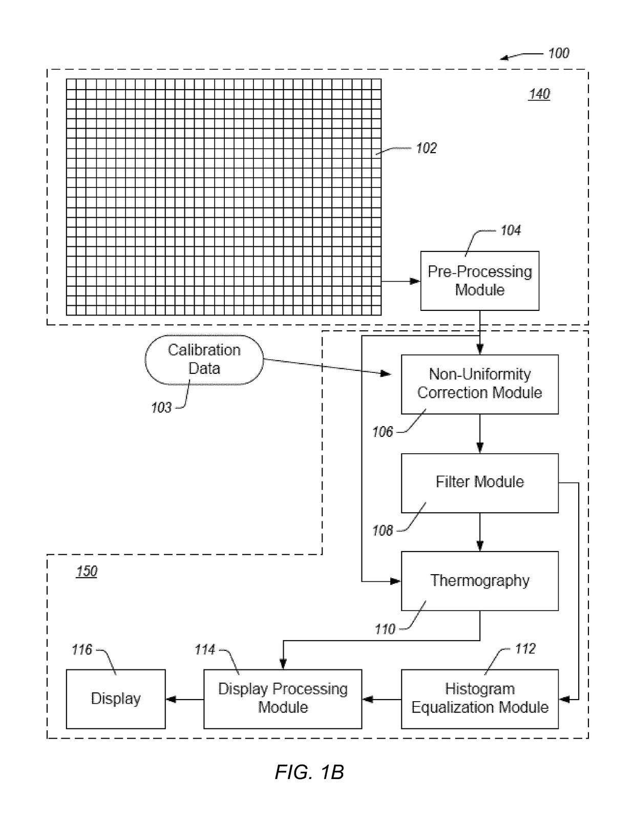
[0045]FIG. 1A illustrates the basic elements of a thermal imaging system, such as a thermal camera, or a thermal camera core interfaced to a computing / display device such as a smartphone or other computing device. Accordingly, as shown in FIG. 1A, the imaging system 100 may generally include optical element 130, an imaging sensor such as a focal plane array 102, at least one processor element 125, and at least one display / user interface element 116. The optics 130, which may be as simple as a single lens, or as complicated as a telescopic zoom optical system, focus thermal energy from a scene onto an imaging sensor, such as an IR FPA 102 as described above. The IR FPA 102 generally converts the light energy to digital image data in the form of image frames comprising image pixels. The image data is provided to at least one processor element 125, which generally performs image processing on the image data, in the form of a series of processing steps often referred to as an ima...

example method

of Selective Color Display of a Thermal Image

[0091]FIG. 6 illustrates an example method 600 of selective color display of a thermal image. The method 600 can be implemented using one or more hardware components in a thermal imaging system or image processing system. For ease of description, the method 600 will be described as being performed by the imaging system 100 described herein with reference to FIGS. 1A and 1B. However, one or more of the steps of the method 600 can be performed by any module, such as the display processing module 114, or combination of modules in the imaging system 100. Similarly, any individual step can be performed by a combination of modules in the imaging system 100 Likewise, the steps of the method can be performed by the thermal imaging system 300 described herein with reference to FIG. 3.

[0092]In block 605, the imaging system receives thermal image data acquired with a thermal image sensor. The imaging system can include the thermal image sensor or th...


PUM


Abstract

An imaging system includes an array of photodetectors configured to produce an array of intensity values corresponding to light intensity at the photodetectors. The imaging system can include a display for display images acquired with the array of photodetectors, after some image and display processing. The image and display processing components of the imaging system produce an array of display-formatted pixels for display on the imaging system display. The display-formatted pixels include at least a first plurality of pixels formatted for display using a first lookup table and a second plurality of pixels formatted for display using a second lookup table. Threshold criteria for choosing which pixels belong to which plurality are determined from analysis of a scene indicated by a user as a background scene. Once the threshold criteria are determined from the background the criteria are applied to pixels in subsequent image frames, and the pixels that meet the criteria are displayed in at least one color table LUT and the pixels that do not are displayed in a at least one different color table LUT. In a particular embodiment. The criteria may be above or below the max scene value (or temperature) from the background scene and pixels below the criteria may be displayed in a monochrome or non-vivid color table and pixels above the criteria are displayed in a vivid color table.

Description

CROSS-REFERENCE TO RELATED APPLICATIONS[0001]This application is a continuation-in-part of U.S. patent application Ser. No. 14 / 851,576, filed Sep. 11, 2015, entitled “SELECTIVE COLOR DISPLAY OF A THERMAL IMAGE,” which in turn claims the benefit of priority from U.S. Provisional Application No. 62 / 049,880, filed Sep. 12, 2014, entitled “SELECTIVE COLOR DISPLAY OF A THERMAL IMAGE,” both of which are incorporated by reference herein in their entirety.BACKGROUNDField[0002]The present disclosure generally relates to color display of a thermal image, and in particular to using different display lookup tables depending on temperatures in a scene.Description of Related Art[0003]The increasing availability of high-performance, low-cost uncooled infrared imaging devices, such as bolometer focal plane arrays (FPAs), is enabling the design and production of mass-produced, consumer-oriented infrared (IR) cameras capable of quality thermal imaging. Such thermal imaging sensors have long been expe...

Claims


Application Information

Patent Timeline
Patent Type & Authority Applications(United States)
IPC IPC(8): H04N9/76H04N5/33H04N9/64H04N9/04G06T7/136H04N9/12
CPCH04N9/76H04N5/33H04N9/646H04N9/04G06T2207/10024H04N9/12G06T2207/20104G06T2207/10048G06T7/136H04N9/43G06T5/007G06T7/11G06T11/60G06T2200/24G06T11/001H04N23/10
Inventor HENRY, BLAKE
Owner SEEK THERMAL
Why Eureka
Try Eureka