
System and Method for Detecting Obstacles in Aerial Systems

Active Publication Date: 2019-01-17
AURORA FLIGHT SCI CORP
View PDF10 Cites 24 Cited by
  • Summary
  • Abstract
  • Description
  • Claims
  • Application Information

AI Technical Summary

Benefits of technology

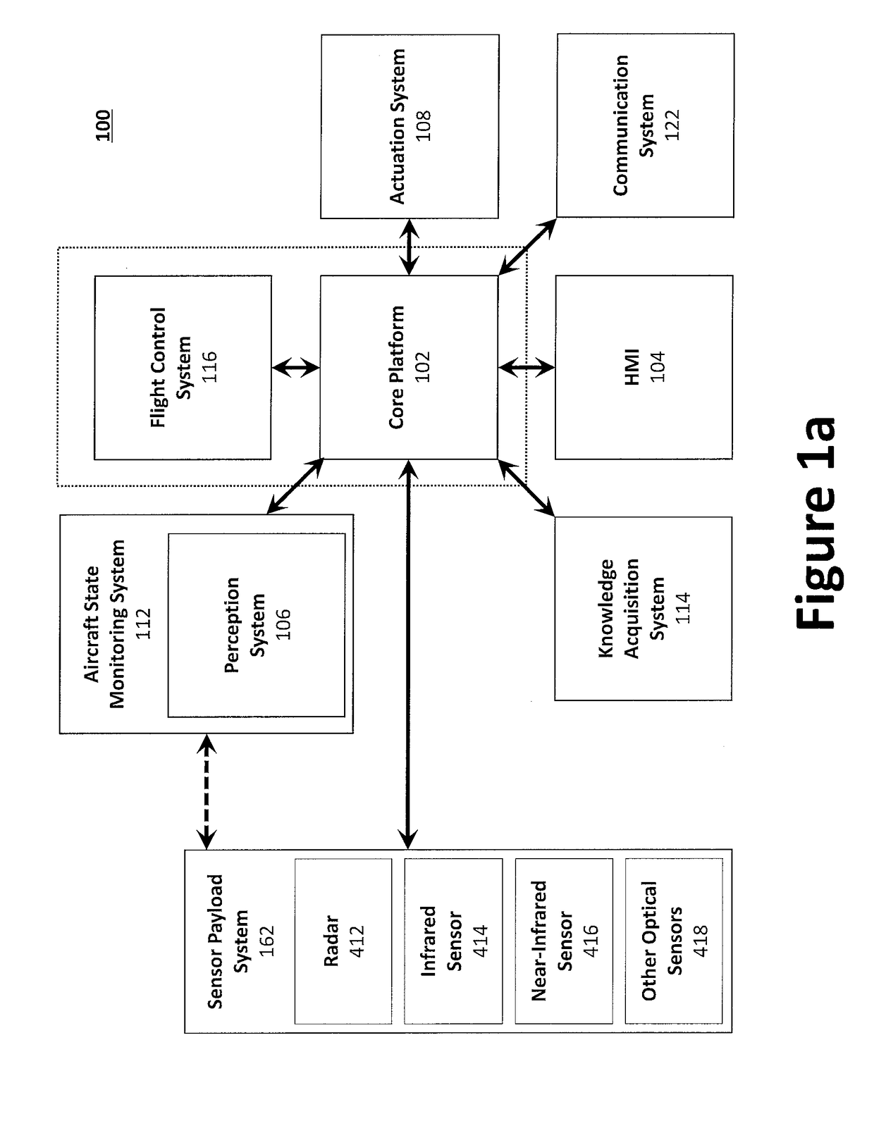
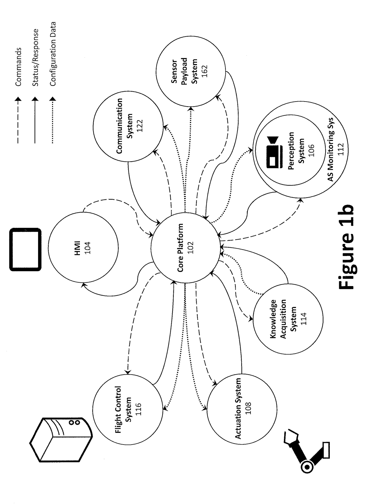
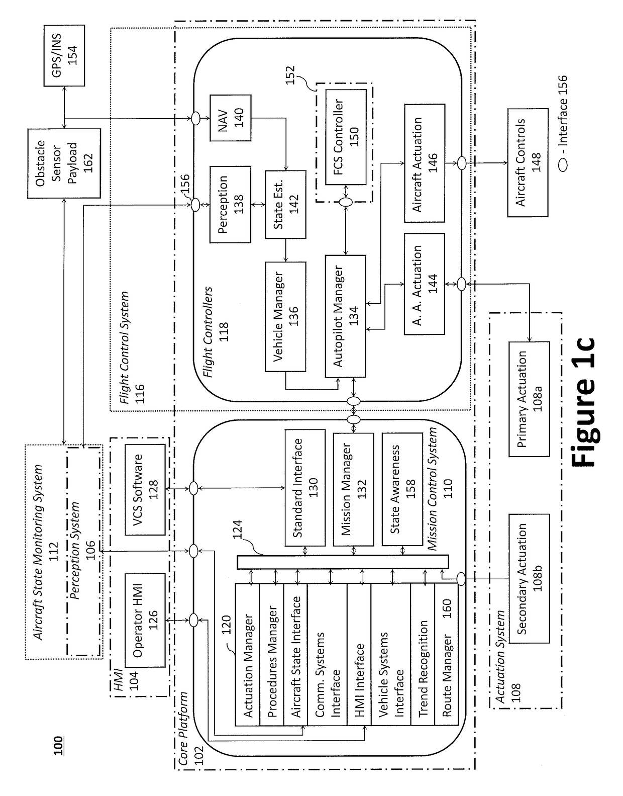
The present invention is about a system, method, and apparatus for detecting and automatically navigating around non-cooperative obstacles in aircraft. The system uses a sensor payload to detect and identify non-cooperative obstacles in the first airspace around the aircraft, and a camera to image the second airspace within the first airspace. The sensor information is combined with optical information to create a 3D representation of the first airspace. The system automatically generates a predicted flight path to avoid the non-cooperative obstacles, and can be used in smaller autonomous aircraft or large aircraft to detect and avoid non-cooperative obstacles. The technical effect of the invention is to improve safety and automation in aircraft operations.

Problems solved by technology

In operation, aircraft may encounter both large and small obstacles within the aircraft's airspace, which may be fixed or moving, and whose position is not known in advance.
Existing technology for preventing aircraft from colliding with obstacles, including Global Positioning System (“GPS”), are generally inadequate as many obstructions cannot be recognized (or quickly recognized) via a GPS device and, depending on the altitude or terrain, GPS accuracy performance varies widely across environments.
While TCAS offers a solution to the problem of detection and avoidance of obstructions for UAVs, TCAS is only able to accomplish this goal if each UAV and obstacle contains a transponder.
Additionally, current flight control systems designed to detect and avoid non-cooperative obstructions utilize costly radar arrays to track obstacle obstructions and are generally only used with large scale aircraft.

Method used


Image

  • System and Method for Detecting Obstacles in Aerial Systems
  • System and Method for Detecting Obstacles in Aerial Systems
  • System and Method for Detecting Obstacles in Aerial Systems

Examples


example

[0200]Aspects of the present disclosure may be illustrated through the following example flight plan, which illustrates how aircrew automation system 100 may interact with the pilot, execute a flight plan, execute flight operational tasks, respond to contingencies during system engagement and takeoff, flight plan engagement, and anomaly detection & handling. The present teachings, however, should not be limited to those used in this example.

[0201]System Engagement and Takeoff.

[0202]The pilot gets into the left seat of an aircraft, fastens the seat belt, positions the human-machine interface 126 comfortably at his side, and activates the aircrew automation system 100 application. The application boots and runs through a series of power-on diagnostics and the mechanical interfaces power up and calibrate. A message may be displayed upon the human-machine interface 126 confirming a successful test and queries the pilot to confirm engagement of aircrew automation system 100. The pilot se...


PUM


Abstract

An automated detection and avoidance system that provides a pilot with high-fidelity knowledge of the aircraft's physical state, and notifies the pilot of any deviations in expected state based on predictive models. The automated detection and avoidance system may include a processor and a sensor payload operatively coupled to the processor to detect a non-cooperative obstacle within a first airspace adjacent the aircraft. The sensor payload may comprise a radar to radially scan the first airspace, and a camera to scan a second airspace within said first airspace.

Description

TECHNICAL FIELD[0001]The present invention relates to the field of flight control systems, methods, and apparatuses; even more particularly, to a system, method, and apparatus for detecting and automatically navigating around stationary and / or moving obstacles.BACKGROUND[0002]Aircraft technology, including unmanned aerial vehicle (“UAV”) technology, is a valuable tool for mission profiles involving intelligence, surveillance, reconnaissance, and payload delivery. In operation, aircraft may encounter both large and small obstacles within the aircraft's airspace, which may be fixed or moving, and whose position is not known in advance. Traditional forms of obstacle detection and avoidance within an aircraft rely on a pilot to provide the critical duty of looking outside the aircraft in order to make sure that the aircraft is not on a collision course with an obstacle, such as another aircraft. Existing technology for preventing aircraft from colliding with obstacles, including Global ...

Claims


Application Information

Patent Timeline
IPC IPC(8): G08G5/04G01S13/86G01S13/93G05D1/10G05D1/00G08G5/00G01S13/933
CPCG08G5/045G01S13/867G01S13/9303G05D1/101G05D1/0088G08G5/0039G01S13/933G05D1/106G01S13/723G08G5/0086G08G5/0078G08G5/04H04N5/33G05D1/10G01C23/00
Inventor CHOI, JAE-WOOSAUNDERS, JEFFREYPADUANO, JAMES D.
Owner AURORA FLIGHT SCI CORP
Features
  • Generate Ideas
  • Intellectual Property
  • Life Sciences
  • Materials
  • Tech Scout
  • Unparalleled Data Quality
  • Higher Quality Content
  • 60% Fewer Hallucinations
Learn More