
Method for determining a doppler frequency shift of a wireless signal directly reflected by a moving object

a wireless signal and wireless technology, applied in the field of wireless signals, can solve problems such as time delay variation, and achieve the effects of accurately determining the frequency, avoiding the effect of the accuracy of the determined frequency, and eliminating the effect of the doppler frequency shift estimation

Active Publication Date: 2019-01-17
PEKING UNIV
View PDF7 Cites 10 Cited by
  • Summary
  • Abstract
  • Description
  • Claims
  • Application Information

AI Technical Summary

Benefits of technology

The present patent describes a method for estimating the frequency spectrum of wireless signals reflected by moving objects using a simple commercial wireless device. The method uses the principle that the path length of the reflected signals changes depending on the object's motion, resulting in time delay variations in the signal phase. By collecting and analyzing the signal at multiple times and using a MUSIC algorithm, the method can determine the frequency of the reflected signals and obtain a frequency spectrum. By eliminating static signals and calculating the highest peak in the spectrum, the method can accurately identify the frequency of the signals reflected by the moving object. The method is fast, cost-effective, and can be easily integrated into existing commercial wireless devices.

Problems solved by technology

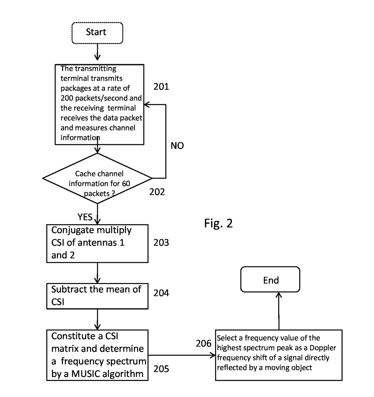
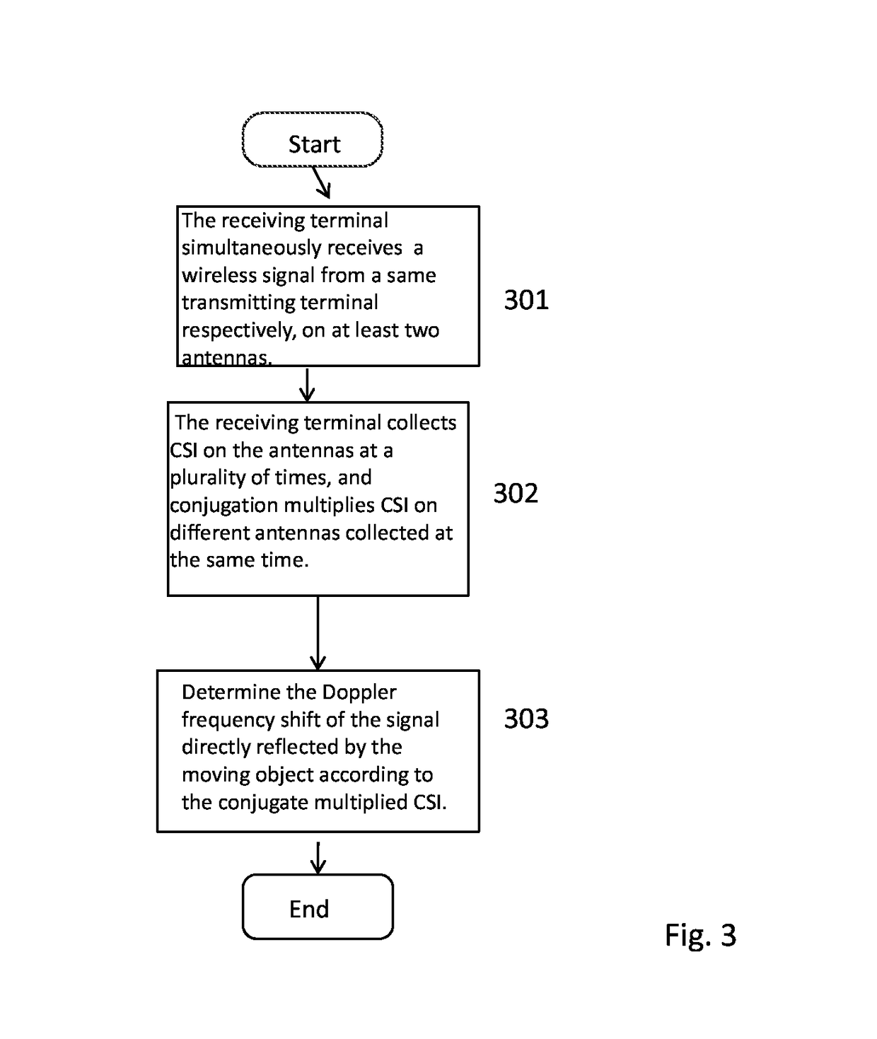
The principle of the present disclosure is: a path length of the wireless signal reflected by the moving object varies with the motion of the object, which results in time delay variation represented on the phase of the CSI.

Method used


Image

  • Method for determining a doppler frequency shift of a wireless signal directly reflected by a moving object
  • Method for determining a doppler frequency shift of a wireless signal directly reflected by a moving object
  • Method for determining a doppler frequency shift of a wireless signal directly reflected by a moving object

Examples


Embodiment Construction

[0045]The present disclosure will now be further described, through the embodiments, with reference to the drawings, but in no way limiting the scope of the present disclosure.

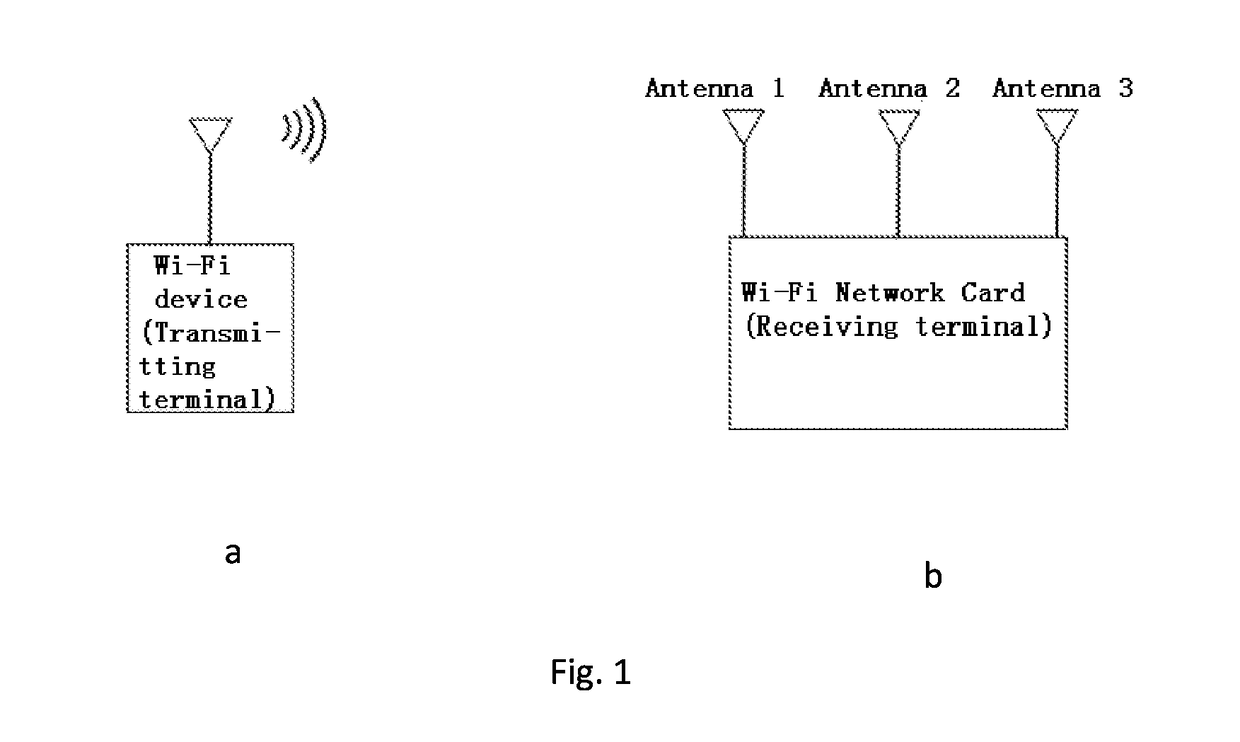
[0046]The present disclosure provides a method for determining a Doppler frequency shift of a wireless signal directly reflected by a moving object, based on a wireless signal multi-antenna transmitting-receiving system and a processing server (a processing system), eliminating a random phase shift caused by the non-synchronization of transmitting-receiving devices through conjugate multiplying the channel state information (CSI) on multi-antennas, after eliminating static path signals by subtracting a mean, taking the CSI of different subcarriers as snapshots, obtaining the frequency spectrum by using the Multiple Signal Classification(MUSIC) algorithm, and further obtaining the Doppler frequency shift of the signal directly reflected by a target object.

[0047]In one embodiment of the present disclosure, a wir...


PUM


Abstract

The present disclosure provides a method for determining a Doppler frequency shift of a wireless signal directly reflected by a moving object. An example method includes eliminating a random phase shift caused by non-synchronization between a wireless transmitting device and a wireless receiving device by using conjugate multiplication of the channel state information (CSI) on two antennas, thereby obtaining the complete Doppler frequency shift information from the phase information of the channel state information. The example method eliminates the effect on the Doppler frequency shift caused by frequency information of static paths in a manner of removing the mean, thereby obtaining an accurate frequency estimation of the moving object. A Multiple Signal Classification (MUSIC) algorithm may be used to estimate a frequency spectrum according to practical sampling intervals to avoid an effect on the frequency estimation accuracy caused by uneven sampling rate in a practical wireless transceiving system.

Description

CROSS REFERENCE TO RELATED APPLICATION[0001]This application claims priority to Chinese Application No. 201710579684.9 entitled “A METHOD FOR DETERMINING A DOPPLER FREQUENCY SHIFT OF A WIRELESS SIGNAL DIRECTLY REFLECTED BY A MOVING OBJECT,” filed on Jul. 17, 2017, the entire contents of which is hereby incorporated by reference in its entirety for all purposes.TECHNICAL FIELD[0002]The present disclosure relates to a technical field of wireless signals, and more particularly to a method for determining a Doppler frequency shift of a wireless signal directly reflected by a moving object.BACKGROUND ART[0003]During transmission, the wireless signal not only arrives at a receiving terminal through a direct path between a transmitting and a receiving device, but meanwhile arrives at the receiving terminal through the reflection of objects (ground, people, wall, furniture, etc.) in a transmission environment as well. This is also known as multi-path propagation. If one of the transmitting ...

Claims


Application Information

Patent Timeline
IPC IPC(8): H04B17/309H04W4/02H04B7/01H04W56/00
CPCH04B17/309H04W56/0035H04B7/01H04W4/027
Inventor ZHANG, DAQINGLI, XIANG
Owner PEKING UNIV
Learn More