Wheel blank positioning lip correction device

a technology for positioning and adjusting the position of the wheel, which is applied in the direction of other manufacturing equipment/tools, grinding machine components, manufacturing tools, etc., can solve the problems of skewing defects of the machined product, failure of the inner and outer rims, etc., and achieves high production efficiency, reasonable layout, and avoids interference of cutter concentration

Active Publication Date: 2019-01-24
CITIC DICASTAL
View PDF11 Cites 8 Cited by
  • Summary
  • Abstract
  • Description
  • Claims
  • Application Information

AI Technical Summary

Benefits of technology

[0004]The aim of the present application is to provide a deformation correction device for the positioning lip of a wheel blank. The device is used for solving the problem of machining rejects caused by deformation of the positioning lip of the wheel blank. The device can correct the deformation of the positioning lip and prevent unqualified blanks from being machined.
[0007]The four guide posts are fixed at the top of the frame, the linear motor I is mounted at the upper part of the frame, the output end of the linear motor I is connected with the feeding slide plate, the linear motor I controls lifting of the feeding slide plate under the guiding effect of the guide posts, the guide rail II and the linear motor II are fixed on the feeding slide plate, the inner slide block is mounted on the guide rail II, and the output end of the linear motor II is connected with the inner slide block and can control motion of the inner slide block in the horizontal direction. The servo motor II is mounted on the inner slide block, the end mill is mounted at the output end of the servo motor II, and the end mill is used for milling and correcting the axial positioning surface of the positioning lip. When the outside diameter of the wheel is changed, the linear motor II can drive the inner slide block to move horizontally so as to adjust the end mill to be located above the positioning lip.
[0010]The device is reasonable in layout, flexible and efficient; the two positioning surfaces to be corrected are separated into two stations, so that the interference of cutter concentration is avoided; and through simultaneous correction at the two stations, the production efficiency is high. Besides, the device is high in flexibility and strong in generality, and can be used for correcting wheels having different outside diameters and different widths.
[0011]The present application may solve the problem of machining rejects caused by deformation of the positioning lip of the wheel blank, reduce the manufacturing cost and improve the qualification rate of the product; and the device is simple in operation, efficient and practical, and meets automatic continuous production.

Problems solved by technology

When the axial positioning surface and radial positioning surface of the cast process lip deform greatly, the machined and clamped wheel skews, and the machined product has the defects of skewing, machining failure of inner and outer rims and the like.

Method used


Image

  • Wheel blank positioning lip correction device
  • Wheel blank positioning lip correction device
  • Wheel blank positioning lip correction device

Examples


Embodiment Construction

[0016]Details and working conditions of a specific device provided by the present application will be given below in combination with the accompanying drawings.

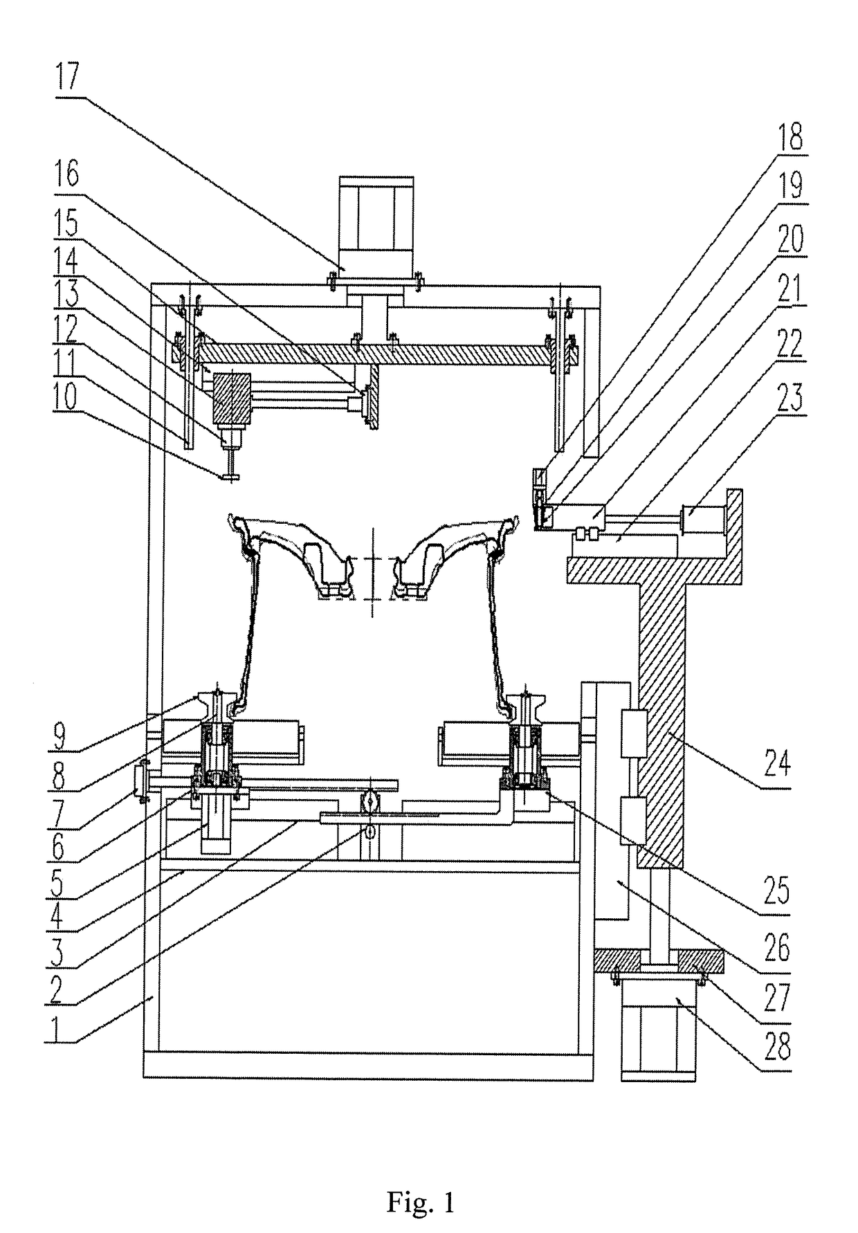
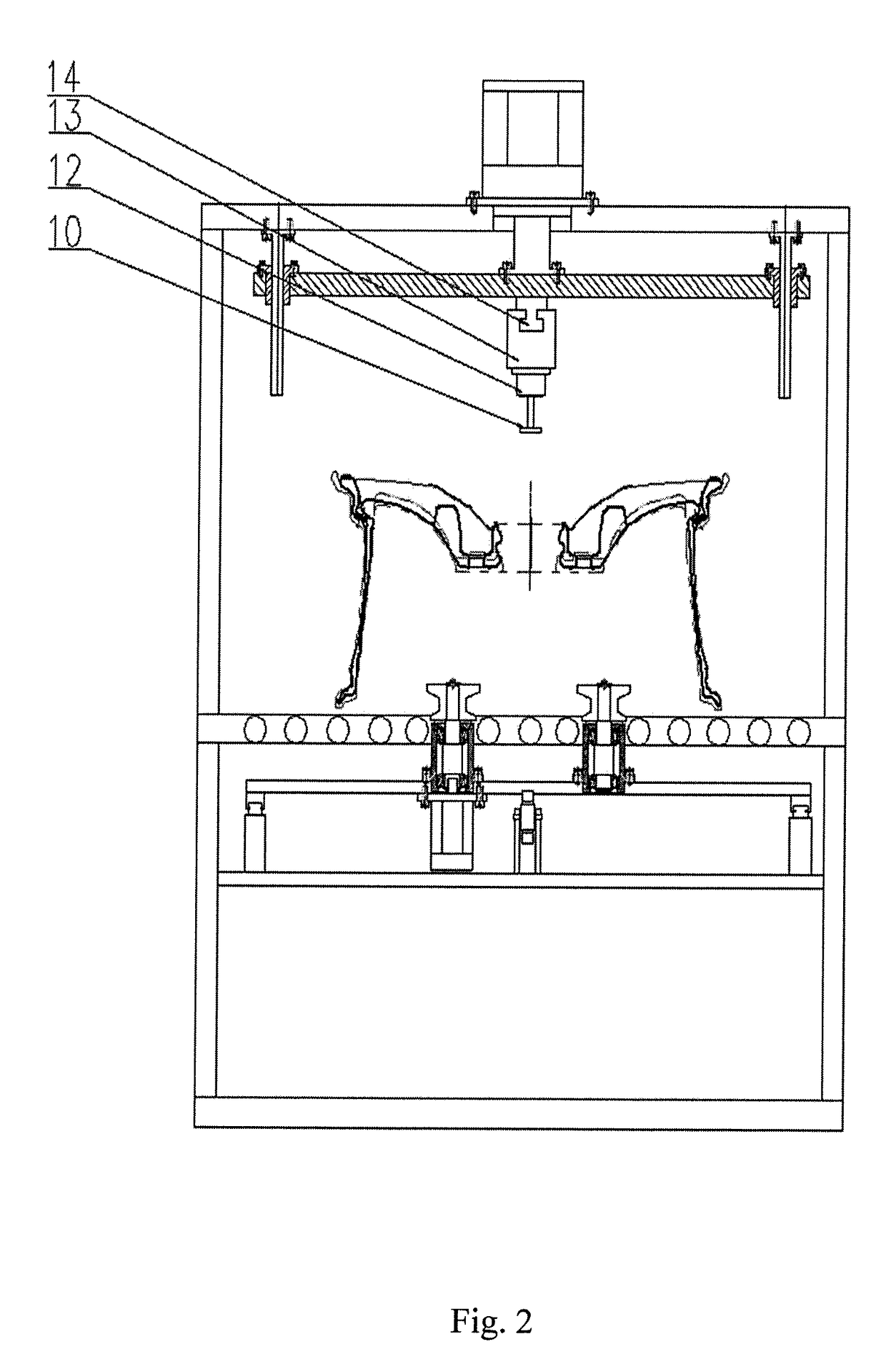
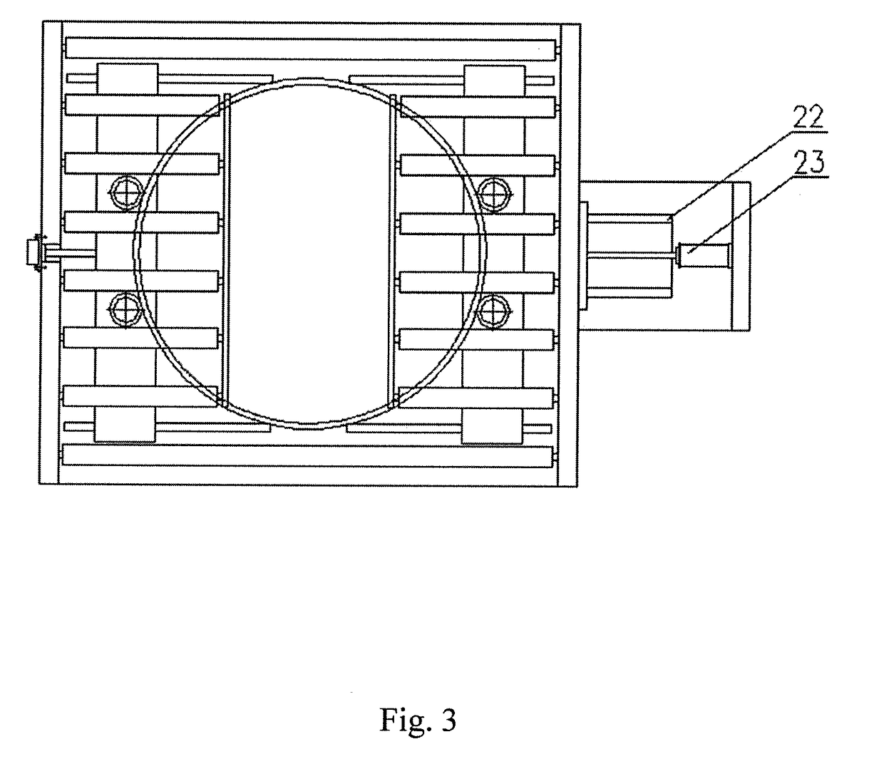
[0017]A wheel blank positioning lip correction device comprises a frame 1, a gear rack structure 2, a guide rail I 3, a clamping system support plate 4, a servo motor I 5, a left slide plate 6, a clamping cylinder 7, a rotating shaft 8, rotating wheels 9, an end mill 10, guide posts 11, a servo motor II 12, an inner slide block 13, a guide rail II 14, a feeding slide plate 15, a linear motor II 16, a linear motor I 17, a servo motor III 18, a shaft 19, a grinding wheel 20, an outer slide block 21, a guide rail III 22, a linear motor III 23, a lifting table 24, a right slide plate 25, a lifting guide rail 26, a motor support plate 27 and a lifting linear motor 28.

[0018]The guide rail I 3 is mounted on the clamping system support plate 4, the left slide plate 6 and the right slide plate 25 are mounted on the guide rail I 3 and ...


PUM


Abstract

Disclosed is a wheel blank positioning lip correction device, comprising a frame, a gear rack structure, a guide rail I, a clamping system support plate, a servo motor I, a left slide plate, a clamping cylinder, a rotating shaft, rotating wheels, an end mill, guide posts, a servo motor II, an inner slide block, a guide rail II, a feeding slide plate, a linear motor II, a linear motor I, a servo motor III, a shaft, a grinding wheel, an outer slide block, a guide rail III, a linear motor III, a lifting table, a right slide plate, a lifting guide rail, a motor support plate and a lifting linear motor.

Description

CROSS-REFERENCE TO RELATED APPLICATIONS[0001]This application claims priority to Chinese Patent Application No. 201710598274.9, filed on Jul. 21, 2017, which is hereby incorporated by reference in its entirety.TECHNICAL FIELD[0002]The present application relates to the technical field of wheel blank positioning lip correction, specifically to a deformation correction device for the positioning lip of a wheel blank.BACKGROUND ART[0003]Adopted in positioning during aluminum alloy wheel machining is a cast process lip, and the cast blank deforms in the cooling process and after thermal treatment, so that the axial positioning surface and radial positioning surface of the cast process lip are raised and sunken. When the axial positioning surface and radial positioning surface of the cast process lip deform greatly, the machined and clamped wheel skews, and the machined product has the defects of skewing, machining failure of inner and outer rims and the like.SUMMARY OF THE INVENTION[000...

Claims


Application Information

Patent Timeline
Patent Type & Authority Applications(United States)
IPC IPC(8): B24B49/12B24B9/04B24B29/00
CPCB24B49/12B24B9/04B24B29/005B23P23/04B24B41/067B24B5/44B23C3/04B23C2215/085B24B27/0076B24B27/0023
Inventor LIU, HUIYINGLU, YUEXINYU, ZHIYUAN
Owner CITIC DICASTAL
Why Eureka
Try Eureka