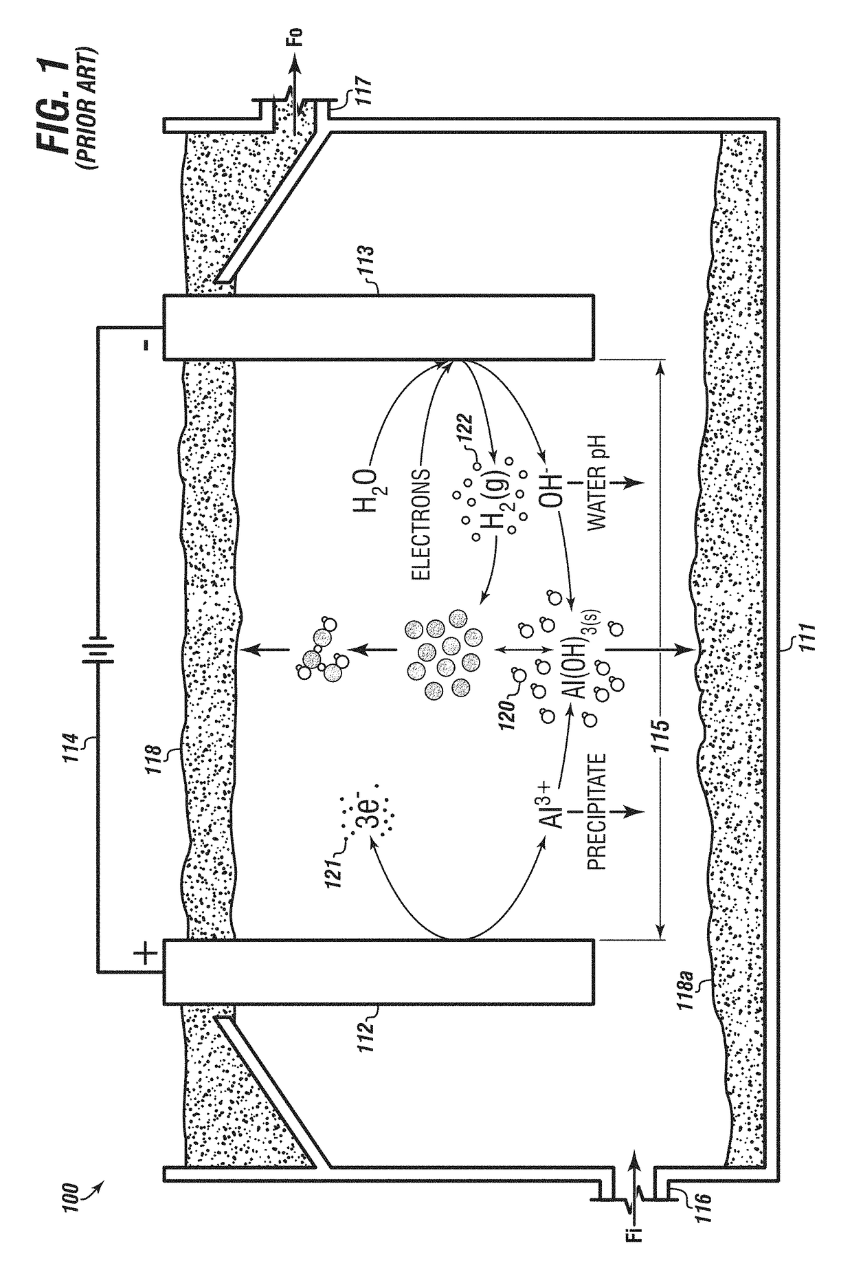
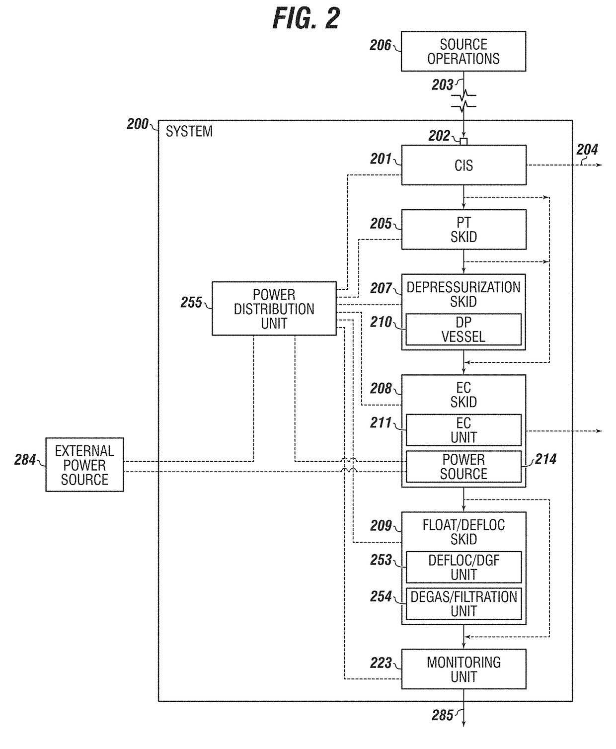
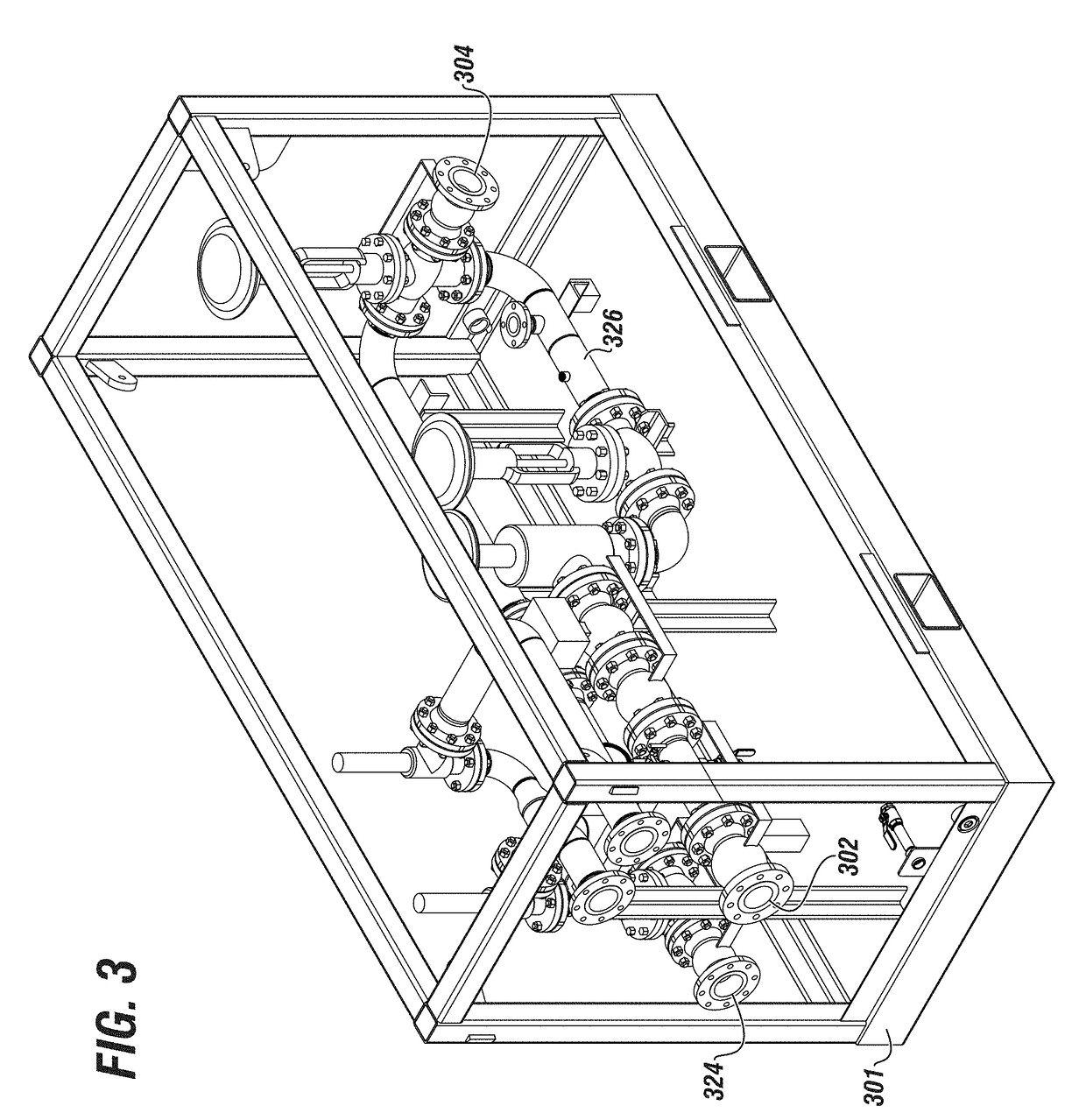
Electrocoagulation unit
a technology of electrocoagulation and coagulation chamber, which is applied in the nature of water treatment, multi-stage water/sewage treatment, water treatment multi-stage treatment, etc. it can solve the problems of high cost, high cost, and high cost of treatment skids
- Summary
- Abstract
- Description
- Claims
- Application Information
AI Technical Summary
Benefits of technology
Problems solved by technology
Method used
Image

Examples
Embodiment Construction
[0068]Herein disclosed are novel apparatuses, units, systems, and methods that pertain to improved fluid treatment and aspects related thereto, details of which are described herein.
[0069]Embodiments of the present disclosure are described in detail with reference to the accompanying Figures. In the following discussion and in the claims, the terms “including” and “comprising” are used in an open-ended fashion, such as to mean, for example, “including, but not limited to . . . ”. While the disclosure may be described with reference to relevant apparatuses, systems, and methods, it should be understood that the disclosure is not limited to the specific embodiments shown or described. Rather, one skilled in the art will appreciate that a variety of configurations may be implemented in accordance with embodiments herein.
[0070]Although not necessary, like elements in the various figures may be denoted by like reference numerals for consistency and ease of understanding. Numerous specifi...
PUM
| Property | Measurement | Unit |
|---|---|---|
| thickness | aaaaa | aaaaa |
| thickness | aaaaa | aaaaa |
| distance | aaaaa | aaaaa |
Abstract
Description
Claims
Application Information