High pressure process and apparatus for the electrocoagulative treatment of aqueous and viscous fluids

a viscous fluid and high pressure technology, applied in the direction of electrostatic separation, machines/engines, sedimentation settling tanks, etc., can solve the problems of complex permitting issues, inability to handle viscous materials such as sludge or slurries, and restrict flow, so as to facilitate maintenance and easy to close

Active Publication Date: 2006-08-08
GAVREL TOM GUS +1
View PDF11 Cites 34 Cited by
  • Summary
  • Abstract
  • Description
  • Claims
  • Application Information

AI Technical Summary

Benefits of technology

[0011]The high pressure plate and frame electrocoagulation vessel of a preferred embodiment of the present invention includes a plurality of recessed, gasketed, non-electrically conductive spacer plates with integral supports on the edges, hereafter referred to as spacer plates, that contain various shaped electrodes within the recessed boundaries of the spacer plates. The spacer plate holds and positions the electrodes in a specific orientation. The integral supports on the edges of the spacer plates accommodate resting on side rails of an elongated frame, preferably square or rectangular. The spacer plate stack can be arranged in various orientations, such as substantially horizontal or substantially vertical. In a preferred embodiment, the electrodes can act as a sacrificial material, including iron or aluminum, such that the electrode material will be sacrificed at the anodes in accordance with Faraday's Law when a voltage is applied to the electrodes. In an alternate preferred embodiment, it is advantageous to include electrodes of non-sacrificial material and / or electrodes coated with a non-sacrificial material. This can be particularly beneficial when the desired effect is oxidation and reduction or organism / organic destruction by the electromotive force present within the device. In a preferred embodiment, the electrodes are slotted, perforated, pierced, or crimped. The electrodes can be constructed of a porous, permeable or semi-permeable material. Other characteristics of electrodes known in the art can be used. Another preferred embodiment of the present invention includes an electrical conduit being external with integral attachment means for attachment to the electrodes for applications in a non-hazardous environment (i.e.: non-explosion proof). The electrical conduit, whether internal or external, includes conductive elements that allow a voltage to be applied to the fluid.
[0012]In one preferred embodiment, the spacer plates are constructed with a plurality of gasketed ports. These gasketed ports align with each other when a plurality of spacer plates are arranged beside each other such that the gasketed ports create a plurality of interconnected channels acting as conduits for fluid flow and for distribution of an applied voltage within the confines of an outer gasket located near the peripheral edge of the spacer plates. The aligned gaskets are referred to jointly as the peripheral gasket. The peripheral gasket of the spacer plates contains all fluids, bores and electrodes such that when the spacer plates are aligned for operation, each bore is substantially isolated from the outside environment. In a preferred embodiment, the spacer plates are aligned by applying closing or operating pressure to the spacers, preferably by hydraulic mechanical closure means. The integral hydraulic mechanical closure means allows for applying and releasing closure pressure on the plurality of spacer plates allowing the apparatus to be easily opened for maintenance and subsequently, easily closed with sufficient pressure to ensure containment and isolation of all fluids and bores within the confines of the apparatus. Another preferred embodiment includes external fluid conduits in fluid communication with an influent and / or effluent mixing chamber, also called a fall chamber, of the apparatus via an external manifold.

Problems solved by technology

Such methods typically suffer from drawbacks such as restricted flow and / or the inability to handle viscous materials such as sludge or slurries.
One shortcoming of the Ramirez teaching is that current environmental standards dictate that fugitive air emissions are unacceptable and present complex permitting issues.
Venting to atmosphere also limits applications in which an apparatus or process may be implemented due to hazardous materials venting to atmosphere and risk of explosion.
The requirement of a defoam tank increases the overall footprint of the apparatus, adds additional plumbing and mixing components and vents off gases to atmosphere.
This is unacceptable in many applications.
This limits the application to low pressure conditions.
Because of the spacing of the plates, when fluid velocities reach a critical point the differential pressure through the reactor cell is too great and the reactor cell is susceptible to leaking creating house keeping issues, exposure of possible hazardous materials to workers and the environment and the release of off gases to the environment.
The Morkovsky reactor cell design is mechanically complex depending on “links” which are a means of connecting electrical power to the electrodes.
These “links” must be inserted between the closely spaced electrode plates and tightened by means of nuts, screws and / or bolts and becomes maintenance intensive when exchanging the electrode plates or performing other maintenance.
This device utilizes a rectangular tank, again open to the atmosphere, non-pressured and is not applicable to viscous fluids or sludges.

Method used


Image

  • High pressure process and apparatus for the electrocoagulative treatment of aqueous and viscous fluids
  • High pressure process and apparatus for the electrocoagulative treatment of aqueous and viscous fluids
  • High pressure process and apparatus for the electrocoagulative treatment of aqueous and viscous fluids

Examples


Embodiment Construction

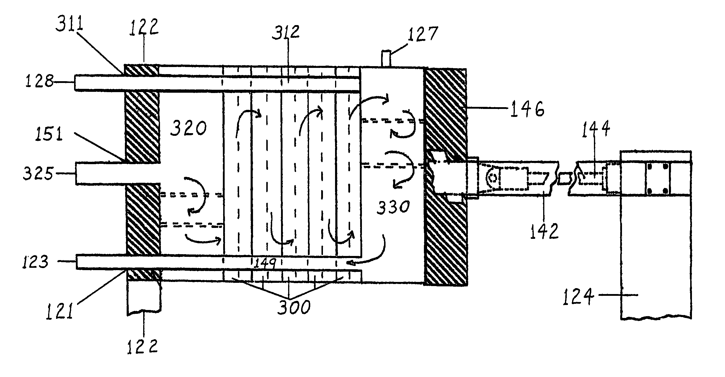
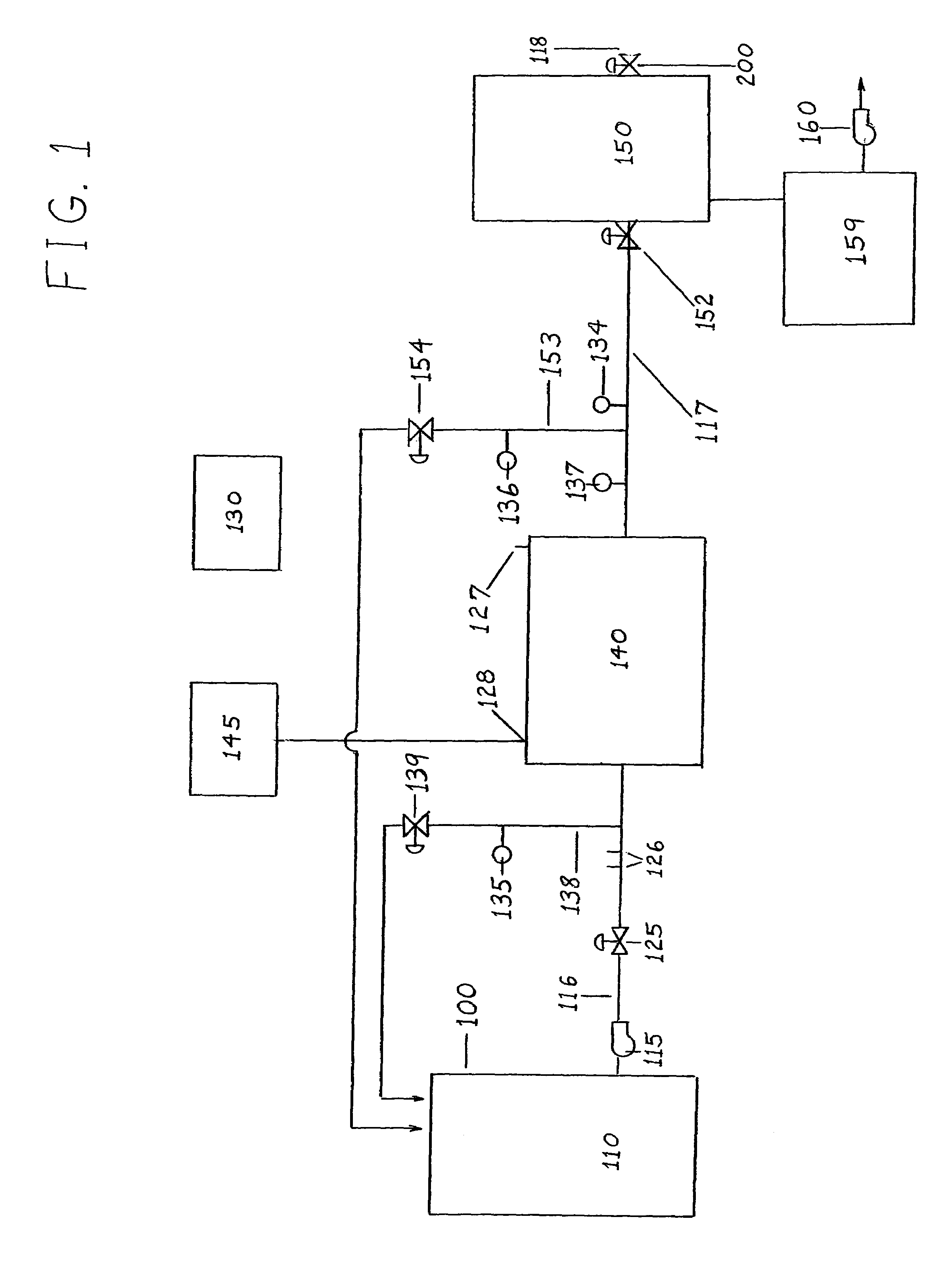
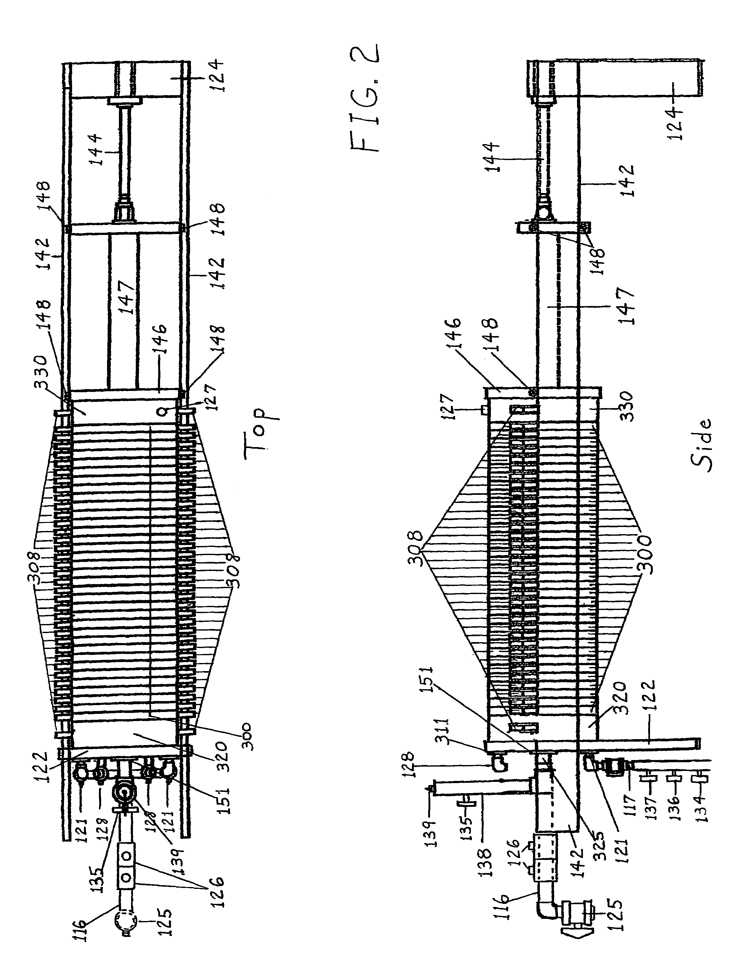
[0039]One preferred embodiment of the invention includes a plate and frame apparatus utilizing recessed, gasketed, non-conductive spacer plates with enclosed, exchangeable electrodes of various designs that are suspended on a supporting, generally square, elongate frame in such a way as to allow the spacer plates with electrodes to be easily separated or opened. This ease of closure provides a simple means to exchange the electrodes or perform other maintenance after which the device is subsequently closed and pressured utilizing a hydraulic or screw type mechanical closure device or the like that can maintain sufficient closure / operating pressure to seal the plurality of spacer plates with enclosed electrodes within the confines of the plurality of chambers formed therein such that the pressurized fluids are isolated within the apparatus. The apparatus of one preferred embodiment advantageously incorporates influent and effluent mixing chambers, which can contain injection ports fo...


PUM

PropertyMeasurementUnit
pressuresaaaaaaaaaa
pressureaaaaaaaaaa
voltageaaaaaaaaaa

Abstract

A method and apparatus for the high-pressure electrocoagulative treatment of aqueous and viscous fluids and sludge is provided. The apparatus includes a plate and frame design utilizing mechanical closure on a plurality of recessed, gasketed, non-electrically conductive electrocoagulation spacer plates that completely enclose and isolate all fluids, electrical contacts, and electrodes within the confines of the apparatus. The spacer plates include intergral supports that position and support said plates with enclosed electrodes on top of the side rails of the supporting frame of the apparatus allowing said plates to be separated for electrode replacement and maintenance and conversly closed, pressured and put into service. The apparatus includes a baffled influent and effluent chamber at both ends for the addition and flash mixing of chemical reagents and/or flocculants and to provide a means of fluid communication between fluid conduits and chambers formed within the apparatus.

Description

RELATED APPLICATIONS[0001]This application claims the benefit of a provisional application having U.S. Ser. No. 60 / 425,358, filed on Nov. 11, 2002, which hereby is incorporated by reference in its entirety.BACKGROUND OF THE INVENTION[0002]1. Field of the Invention[0003]The present invention relates to a high pressure method and apparatus for the treatment of aqueous or viscous fluids to destroy or otherwise render harmless undesirable living organisms in the fluids. A method and apparatus for removal of undesirable matter is also included.[0004]2. Description of the Related Art[0005]Various methods and apparatus are currently used for the treatment and / or removal of undesirable matter and organisms present in solution, in suspension or in a stable state of emulsion in aqueous fluids. Such methods typically suffer from drawbacks such as restricted flow and / or the inability to handle viscous materials such as sludge or slurries. Specific electrocoagulative treatment methods and appara...

Claims


Application Information

Patent Timeline
Patent Type & Authority Patents(United States)
IPC IPC(8): C02F1/463C25B9/00B01D21/00C02F1/00C02F1/38C02F1/44C02F1/461C02F1/465C02F1/467C02F11/00C02F11/12
CPCB01D21/0009B01D21/0042B01D21/0066B01D21/02B01D21/305C02F1/463B01D21/0039C02F2301/066C02F2209/005C02F1/38C02F1/444C02F1/46109C02F1/465C02F1/4672C02F11/00C02F11/121C02F2001/46123C02F11/15
Inventor GAVREL, TOM GUSVINSON, IRA B.OTTO, DAVID WAYNE
Owner GAVREL TOM GUS
Why Eureka
Try Eureka