
Contaminant removal apparatus and installation method

a technology of contaminant removal and installation method, which is applied in the direction of centrifugal separation, water/sewage treatment, water treatment parameter control, etc. it can solve the problems of increasing the restrictions and stringentness of older methods of contamination removal or water purification, insufficient efficiency of meeting stricter water purity standards, and other methods of wastewater treatment are expensive. , to achieve the effect of rapid and unnecessary depletion of electrodes, high efficiency and cost-effectiv

Inactive Publication Date: 2005-11-10
AQUENOX
View PDF2 Cites 32 Cited by
  • Summary
  • Abstract
  • Description
  • Claims
  • Application Information

AI Technical Summary

Benefits of technology

[0025] It will be appreciated that the results obtained from steps (ii) and (iii) can be determined and checked experimentally as described above and provide a highly efficient and cost effective method of installation of an electrocoagulation system to a factory site which processes wastewater that can comprise a number of different types of wastewater streams as described above. If the configuration of the electrocoagulation cell is not set-up correctly taking into account the abovementioned parameters for the specific contaminant composition of the wastewater, efficient removal of the contaminants will not occur.
[0026] In relation to steps (ii) and (iii) having regard to the bench-type EC system, it is possible to determine voltage and current in categories of low (L), medium (M) and high (H) values, wherein L, M and H in relation to ranges of voltage and current are given in Example 3.
[0027] Thus it is suitable to provide voltage and current in nine separate classifications i.e. L-L, L-M, L-H, M-L, M-M, M-H, H-L, H-M, and H-H. Thus for example, when the conductivity value is low and the voltage-current classification is H-H, then it is usual to have all 8 electrodes of the EC cell electrically connected. When the conductively value is high and the voltage-current classification is L-L then it is usual to have only 2 electrodes of the 8 electrodes electrically connected.
[0028] However it must be pointed out that usually if an L-L classification is obtained no reaction may occur in the EC cell and if a H-H classification is obtained this is undesirable because more rapid and unnecessary depletion of the electrodes may occur.
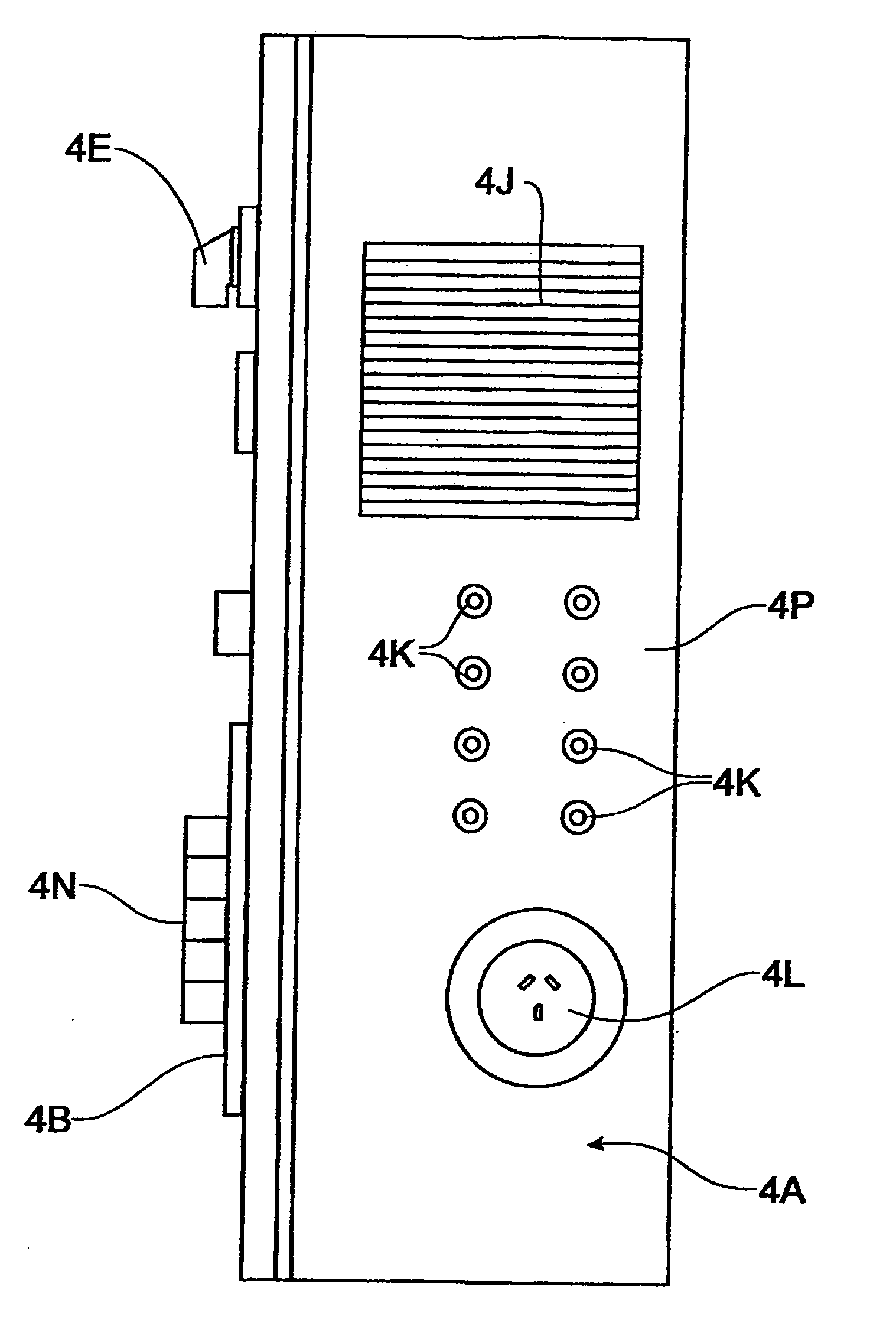
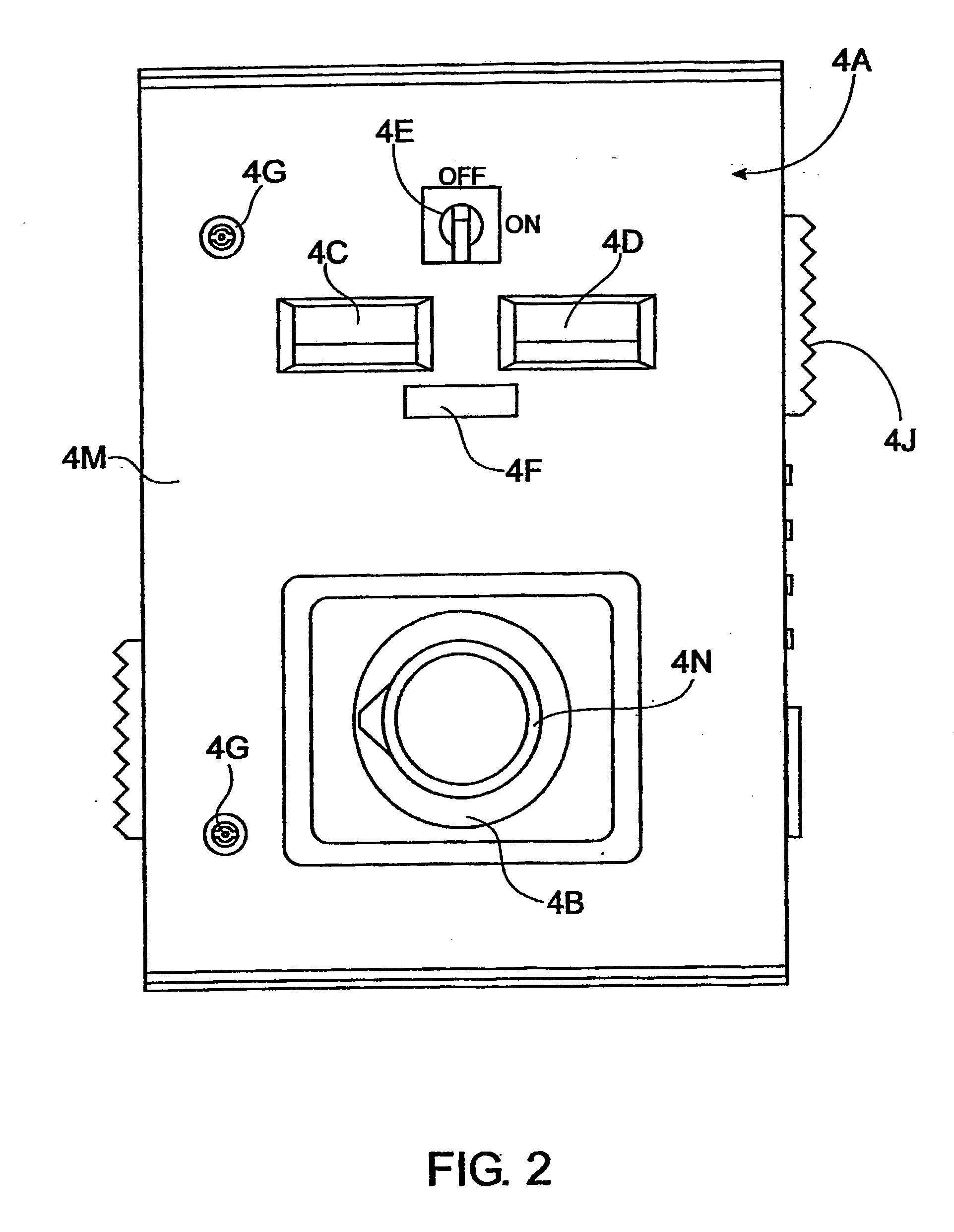
[0029] The method of determination of the voltage-current classification may be determined from knowledge of the sample matrix having regard to the criteria given above and use of a variac which is adjustable to increase or decrease voltage and current. The variac may be part of the EC cell in the bench-type EC system as hereinafter described in relation to the preferred embodiment in FIGS. 2-3.

Problems solved by technology

Water purity regulations, which specify acceptable levels for a wide range of contaminants in water discharged into waterways, sewer systems or discharged in other manners, are becoming more restrictive and stringent.
Older methods of contamination removal or water purification are not suitably efficient for meeting the stricter water purity standards that are now demanded.
Other methods of wastewater treatment are expensive and require the addition of chemicals to the wastewater.
Addition of conductants, in particular NaCl, is generally not a desirable objective especially if the purified water is ultimately destined for human consumption or fresh water waterways.
Removal of NaCl from water is very difficult and also very expensive.
Although such electrocoagulation process systems may adequately serve to remove certain contaminants from wastewater, one problem of such systems is that they are overly complicated and not suitable for all types of contaminants.
None of the systems can deal with the variability, concentration and number of contaminants found in industrial and human waste.
The systems do not demonstrate the flexibility required to efficiently remove contaminants from a wide variety of wastewater.
In other words, such systems employ unnecessary components that are only concerned with specific forms of wastewater.

Method used


Image

  • Contaminant removal apparatus and installation method
  • Contaminant removal apparatus and installation method
  • Contaminant removal apparatus and installation method

Examples


example 1

[0089] The following examples apply to all radioactive species including uranyl oxide such as U3O8.

(a) Electrocoagulation Parameters for a Fixed Flow Rate of 100 litres / minute and Cell Residence Time of 6.99 seconds

[0090] The electrocoagulation cell comprises 25 electrodes with a gap of 3 mm between each electrode. The total wetted electrode surface area is 8.16 m2. Electrical connections to a DC power supply are made to 9 electrodes. If the solution conductivity is 330±15% μS / cm, the cell requires 75±15 volts and 314±15% amps.

(b) Electrocoagulation Parameters for a Fixed Flow Rate of 100 litres / minute and Cell Residence Time of 6.99 seconds

[0091] The electrocoagulation cell comprises 25 electrodes with a gap of 3 mm between each electrode. The total wetted electrode surface area is 8.16 m2. Electrical connections to a DC power supply are made to 9 electrodes. If the conductivity is 630 μS / cm, the cell requires 55±15% volts and 404±15% amps.

(c) Electrocoagulation Parameters ...

example 2

[0094] The following example applies to installation of an electrocoagulation system for the removal of free and complex cyanide species from wastewater from an industrial process such as aluminium smelters. The wastewater can contain free cyanide ions, such as sodium cyanide, and complexed cyanides such as sodium ferdcyanide and ferrocyanide. Water purity regulations, which specify acceptable levels for a wide range of contaminants in water discharged into waterways, sewer systems or discharged in other manners, dictate that the total cyanide content of discharged water is less than 0.1 mg / L. The EC system used in this example is similar to that shown in FIGS. 4-7.

[0095] If the pH of the wastewater is greater than 8.2, an acid solution such as that described above in relation to the FIGS. 4-7 embodiment is added to the wastewater.

[0096] If the pH of the wastewater is less than 7.0, an alkali solution such as that described above in relation to the FIG. 5 embodiment is added to th...

example 3

[0107] Table 1 shows the desired range of voltage and current to be applied to an EC cell and the optimum electrode type for effective removal of a list of contaminants.

[0108] Table 1 also shows that the installation method of the invention may also be used in relation to treatment of wastewater containing high BOD (Biological Oxygen Demand) and high COD (Chemical Oxygen Demand) to reduce values to those suitable for discharge.

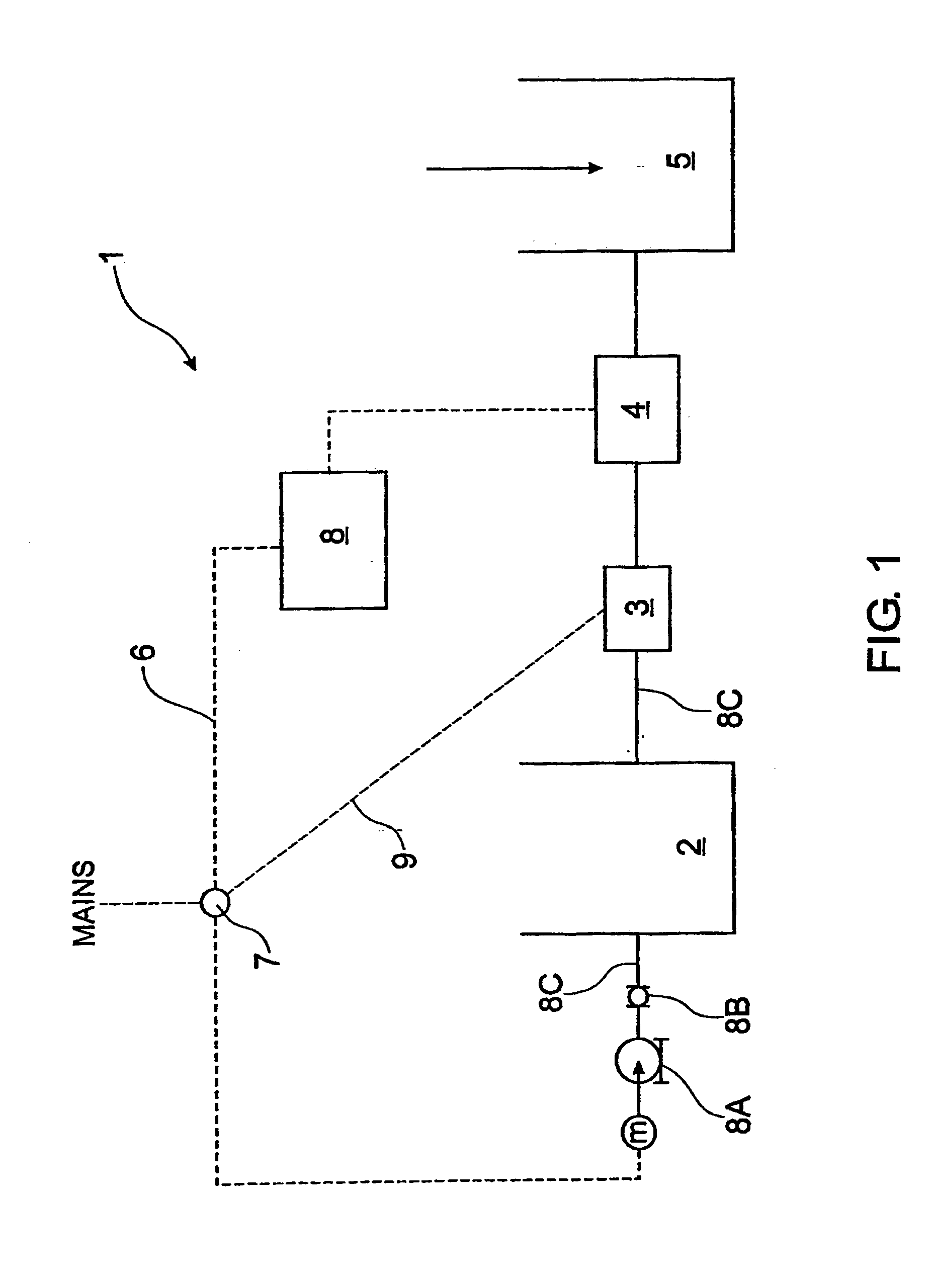
[0109] All experimental data was carried out using the bench-type EC system of FIG. 1 and steps (i) to (iii) of the installation method. Experimentation was required to achieve the optimum experimental parameters.

[0110] An 8 electrode system was used and the number of electrodes connected to the power supply (i.e. unipolar electrodes) depended on the conductivity of the wastewater sample. The number of unipolar connections was calculated as a function of varying wastewater conductivities. 2 unipolar electrodes were used for wastewater with high conductivity...


PUM

PropertyMeasurementUnit
conductivityaaaaaaaaaa

Abstract

This invention relates to a method of installation of an electrocoagulation (EC) system to remove contaminants from wastewater which includes the steps of: (i) measuring conductivity of the wastewater; (ii) from the result obtained in step (i) determining the number of electrically connected electrodes or unipolar electrodes required in the EC system for efficient removal of the contaminants, and (iii) from step (ii) assessing a range of current and / or voltage to be applied to an EC cell included in the EC system.

Description

FIELD OF INVENTION [0001] This invention is concerned with methods of removing contaminants, impurities, additives and / or hazardous materials from aqueous waste streams from industrial, mining or nuclear processes, contaminated bodies of water, sewage, abattoirs, laundrettes, hotels and car washes. In particular, the invention relates to a method of installation of an electrocoagulation apparatus that can remove metal species, oils, greases, detergents, suspended matter, petrochemicals, biological and non-biological organic compounds and the like from wastewater. BACKGROUND OF THE INVENTION [0002] Treatment and recycling of wastewater is an increasingly essential utility worldwide as waterways and ground water become increasingly is polluted by industrial and human waste. In conditions where water is at a premium, such as geographical areas that have very little rainfall, ships and aeroplanes, water recycling is essential. [0003] Water purity regulations, which specify acceptable le...

Claims


Application Information

Patent Timeline
Patent Type & Authority Applications(United States)
IPC IPC(8): C02F1/00C02F1/38C02F1/461C02F1/463C02F1/66C02F9/00
CPCC02F1/38C02F1/46109C02F1/463C02F1/66C02F9/00C02F2001/46128C02F2301/022C02F2101/006C02F2201/46125C02F2201/46145C02F2209/001C02F2209/05C02F2209/06C02F2001/46133
Inventor GRIGG, BRIAN
Owner AQUENOX
Learn More