Fibrous web dewatering appartus and method

a fibrous web and fibrous technology, applied in the field of fibrous web dewatering appartus and method, can solve the problems of reducing the control of dewatering, reducing the moisture uniformity across the fibrous web, and reducing the capacity of paper machines, so as to improve the uniformity, and reduce the turbulence of the machine room.

Active Publication Date: 2019-01-24
KIMBERLY-CLARK WORLDWIDE INC
View PDF5 Cites 1 Cited by
  • Summary
  • Abstract
  • Description
  • Claims
  • Application Information

AI Technical Summary

Benefits of technology

[0006]Accordingly, one advantage of the present invention is that it enables the addition of steam to the fibrous web at velocities that equal or exceed the velocity of machine room air, as measured along the steam box's trailing edge. For example, in certain embodiments steam velocity may be equal to or greater than the velocity of air along the trailing edge, such as about 1.5 times greater, such as from about 1.5 to about 5.0 times and more preferably from about 2.0 to about 3.0 times greater, than the velocity of machine room air. Without being bound by any particular theory, it is believed that by increasing the velocity of steam relative to machine room air the steam may more uniformly be applied to the web and therefore transfer energy to the water within the web more uniformly as it cools and condenses on the web surface.
[0007]Another advantage of the present invention is that the curved bottom plate reduces machine room air turbulence as it is drawn along the plate towards the vacuum dewatering surface in the vacuum zone. Reducing machine room air turbulence in the vacuum zone further improves the uniformity with which steam contacts the web and enables the steam to transfer more energy to the web to facilitate dewatering.
[0008]Yet another benefit of the instant invention is that it permits the vacuum apparatus to pull air from the machine room with less turbulence and at lower velocity with fewer eddies which minimizes the amount of air pulled from beneath the web and prevents damage to the web.
[0009]Still another benefit of increasing steam velocity relative to air velocity is that it may improve the amount of steam that is captured by the vacuum dewatering apparatus and reduces the amount of steam that is expelled to the machine room.
[0010]Thus, in one aspect the present invention provides a vacuum dewatering apparatus comprising a vacuum box having an apertured cover disposed opposite of a steam box, the steam box comprising a bottom plate having a substantially flat portion and a curvilinear portion, at least a portion of the curvilinear portion comprising a plurality of apertures, wherein at least a portion of the apertures are disposed on the bottom plate opposite at least a portion of the apertures disposed on the vacuum dewatering apparatus cover.
[0011]In another aspect the present invention provides a steam box comprising a steam housing in sealed communication with a steam inlet, the steam housing a having an apertured bottom plate, the cross-sectional shape of the apertured bottom plate having a curvilinear portion and a linear portion.

Problems solved by technology

The use of a conventional steam box with a vacuum dewatering system to improve paper machine capacity however, has its limitations.
The result is reduced moisture uniformity across the fibrous web and a reduced control of dewatering.
Another disadvantage of conventional steam boxes is that the amount of steam condensed in the web is largely dependent upon the porosity of the sheet and the capacity of vacuum available.
If the steam flow is increased to a point where either of these limitations is exceeded, excess steam will blow out into the machine room.
This problem becomes evident when the known compartmented hoods attempt to cope with wet streaks.

Method used


Image

  • Fibrous web dewatering appartus and method
  • Fibrous web dewatering appartus and method

Examples


Embodiment Construction

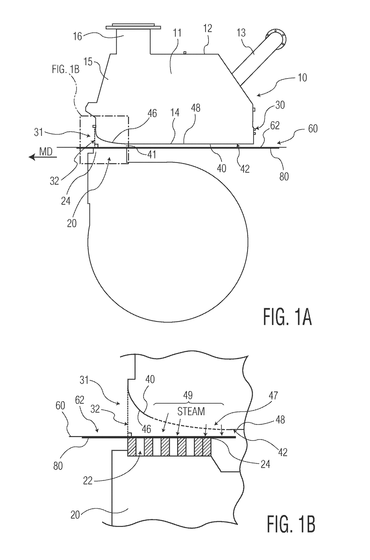
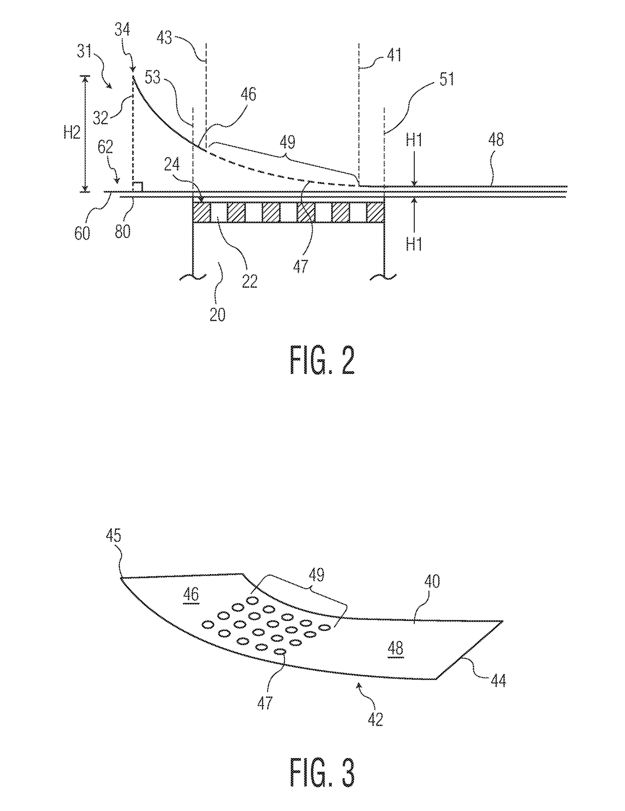
[0018]As is common in the art, the instant vacuum dewatering apparatus comprises a steam box which impinges steam onto a fibrous web, and more particularly a wet fibrous web comprising wood pulp fibers and water, supported on a travelling papermaking belt. The steam heats the water in the web causing its viscosity and surface tension to be reduced. The heated water, with its reduced viscosity and surface tension, may be removed from the web by a vacuum dewatering apparatus. In this manner, in one particular embodiment, the steam box of the present invention may be paired with a vacuum box to partially dewater a fibrous web being conveyed on a papermaking belt.

[0019]Generally the steam box of the present invention is useful in the manufacture of fibrous products, and particularly tissue products having basis weights less than about 100 grams per square meter (gsm) and more preferably less than about 70 gsm, such as from about 10 to about 100 gsm and more preferably from about 15 to a...


PUM


Abstract

The present disclosure relates to a vacuum dewatering apparatus comprising a vacuum box disposed opposite of a steam box where the steam box comprises a bottom plate having a substantially linear portion and a curvilinear portion. A plurality of apertures are disposed along at least a portion of the curvilinear portion to permit the transmission of steam. In a preferred embodiment, the curvilinear portion is adjacent to the trailing edge and the linear portion is adjacent to the leading edge of the apertured bottom plate. Further, at least a portion of the apertures are aligned opposite the vacuum box which acts to remove the steam. The vacuum dewatering apparatus of the present invention enables the use of high levels of steam improving vacuum dewatering and improving drying efficiency.

Description

BACKGROUND OF THE DISCLOSURE[0001]Steam boxes are commonly used in the manufacture of paper products to improve dewatering of fibrous webs at various locations on the paper machine. Steam boxes may be used to improve dewatering by impinging steam onto the fibrous web as it is conveyed through the papermaking process while simultaneously subjecting the web to a vacuum. The increase in temperature caused by the steam reduces the viscosity and surface tension of the water within the web, resulting in more efficient removal by the vacuum.[0002]To facilitate removal of water from the fibrous web the steam box may be installed in the wire section of the paper machine after formation of the fibrous web, in which case the steam box may be used to increase the temperature of the fibrous web to drain the warmed water more easily and thus increase the dry content and improve the drying capacity of the dryer section. By means of steam boxes it is, for instance, possible to increase the capacity...

Claims


Application Information

Patent Timeline
Patent Type & Authority Applications(United States)
IPC IPC(8): D21F1/52D21F7/00
CPCD21F1/52D21F7/008
Inventor SEYMOUR, ROBERT JAMESHASSMAN, MARK JOHNBESAW, CRAIG STEVENRAMAZANI-REND, REZARUDOLPH, JASON MICHAELJENN, THOMAS MCLACHLANCHAI, LUCIA YIYINELSON, SAMUEL AUGUST
Owner KIMBERLY-CLARK WORLDWIDE INC
Why Eureka
Try Eureka