Vibration absorber having an electromagnetic brake for wind turbines

a technology of vibration absorber and electromagnetic brake, which is applied in the design characteristics of springs/dampers, the functional characteristics of springs/dampers, dynamo-electric machines, etc., can solve problems such as interference effects, and achieve the effect of increasing friction and increasing friction

Active Publication Date: 2019-01-24
FM ENERGIE GMBH& CO KG
View PDF0 Cites 6 Cited by
  • Summary
  • Abstract
  • Description
  • Claims
  • Application Information

AI Technical Summary

Benefits of technology

[0023]Alternatively or also in addition, it is possible to coat the entire electromagnet with a brake lining in a thickness of 0.5 mm to 1 mm. The friction-afflicted surface of the brake lining (102) can consist, for example, of a plastic or also of an organic material having a high coefficient of friction. Examples thereof are polyurethanes, in particular polyester-urethane elastomers, such as, in particular, Vulkollan®, which has very low wear for these purposes, so that it is sufficient if the brake lining only projects 0.5-1 mm.
[0026]The rotation mass component (510) should in accordance with the invention have an adjustable variable rotating mass (512, 701), which corresponds to 1%-30% of the absorber mass (1), depending on the diameter. The rotation mass component (510) essentially comprises a driven flywheel (611, 711) with drive axle or shaft and optionally a roller bearing and one or more mass discs (512, 701) or disc segments thereof, which can be pushed onto the axle or shaft of the flywheel or attached thereto and rotate together with the flywheel. The rotation mass component (510) has an adjustable variable rotating mass (512, 701), which preferably corresponds to 1%-30% of the absorber mass (1), depending on the diameter. In a further embodiment, the flywheel (611, 711) has a device which enables the diameter of the mass discs or mass disc segments of the rotation mass component to be changed, or the centre of gravity of the rotating discs or disc segments to be changed radially outwards or inwards. Furthermore, it is also possible to employ mass discs of different diameter. This facilitates variable frequency adaptation of the absorber and damping by the absorber.
[0028]The running device (507) has one, preferably two, parallel running rails (for example two T rails) on which the running gear (508) with the absorber main mass (1) and the rotating flywheel mass (510) can be moved to and fro on the running device on at least two running wheels or running rollers. In a preferred embodiment, at least one running rail and / or at least one running wheel of the running device (507) is provided with a coating, impression or surface structure for the running surfaces which increases the friction forces. For improved adhesion and increased friction, at least some of the drive or running wheels have a friction-increasing running surface structure. In a particular embodiment, the impression comprises a toothed belt or tooth structure. For further improvement, a slip clutch (700) may also be integrated into the drive system of the rotation mass component (510).
[0029]The rolling pendulum absorber described which is fitted with a brake device according to the invention is eminently suitable for damping vibrations below 5 Hz, in particular <1 Hz, in particular <2.5 Hz, preferably between 0.1 and 0.25. For the corresponding frequency changes, only small masses of about 1 / 20 to ¼, preferably about 1 / 10, of the swinging main mass are necessary here, which is a significant advantage over comparable swinging absorbers of the prior art. Thus, the frequency of a swinging main mass of 250 kg can be changed by 20-30% using a rotation mass of around 65 kg with a diameter of 0.25 m in the case of a length of the running device of 2.5 m-3.5 m. The same effect only requires a rotation mass of around 15 kg in the case of a diameter of the rotation mass of 0.5 m and a rotation mass of about 7 kg in the case of a diameter of 0.75 m. Furthermore, the frequency of a swinging main mass of 500 kg can be changed by 20-30% using a rotation mass of around 130 kg with a diameter of 0.25 m in the case of a length of the running device of 2.5 m-3.5 m. The same effect only requires a rotation mass of around 30 kg in the case of a diameter of the rotation mass of 0.5 m and a rotation mass of about 15 kg in the case of a diameter of 0.75 m. Furthermore, the frequency of a swinging main mass of 1000 kg can be changed by 20-30% using a rotation mass of around 250 kg with a diameter of 0.25 m in the case of a length of the running device of 2.5 m-3.5 m. The same effect only requires a rotation mass of around 65 kg in the case of a diameter of the rotation mass of 0.5 m and a rotation mass of about 30 kg in the case of a diameter of 0.75 m.
[0032]The absorbers according to the invention, in particular the particularly advantageous rolling pendulum absorbers, exhibit excellent damping properties in towers and nacelles of wind turbines, but also in the case of other tall and slim structures that are subjected to vibrations, in a variably adjustable frequency range which is matched to the inherent frequencies of the vibration system to be damped, in the case of wind turbines in a range preferably between 1 and 20 Hz. As already mentioned, the brake device also makes it possible to carry out fine tuning of the frequency of the absorber, also making it possible to select values which are slightly above or below the inherent frequency of the installation in order thus to counter certain vibration problems.

Problems solved by technology

The side peaks arising in the case of these undamped systems are particularly high and can therefore have interfering effects.

Method used


Image

  • Vibration absorber having an electromagnetic brake for wind turbines
  • Vibration absorber having an electromagnetic brake for wind turbines
  • Vibration absorber having an electromagnetic brake for wind turbines

Examples


Embodiment Construction

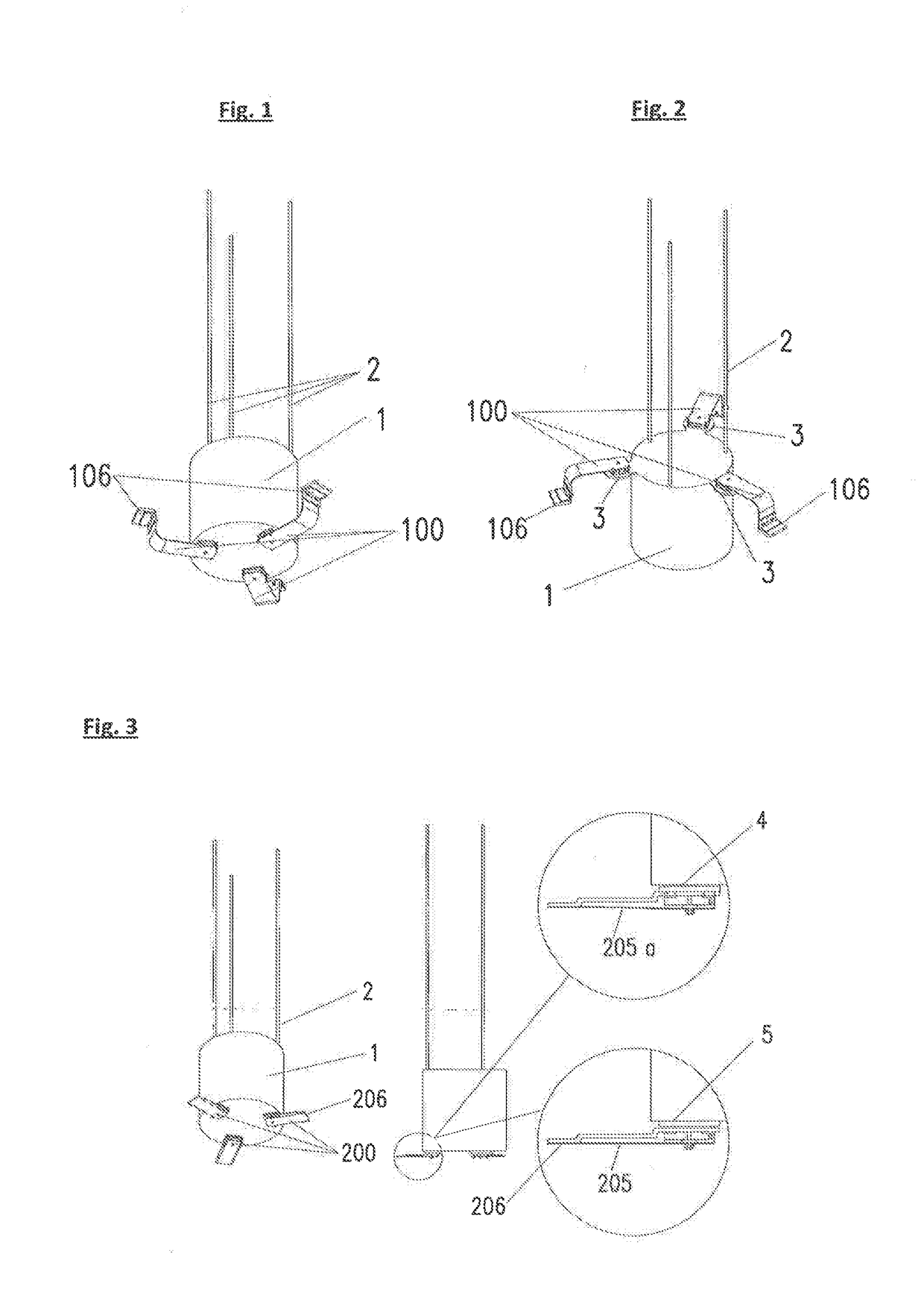
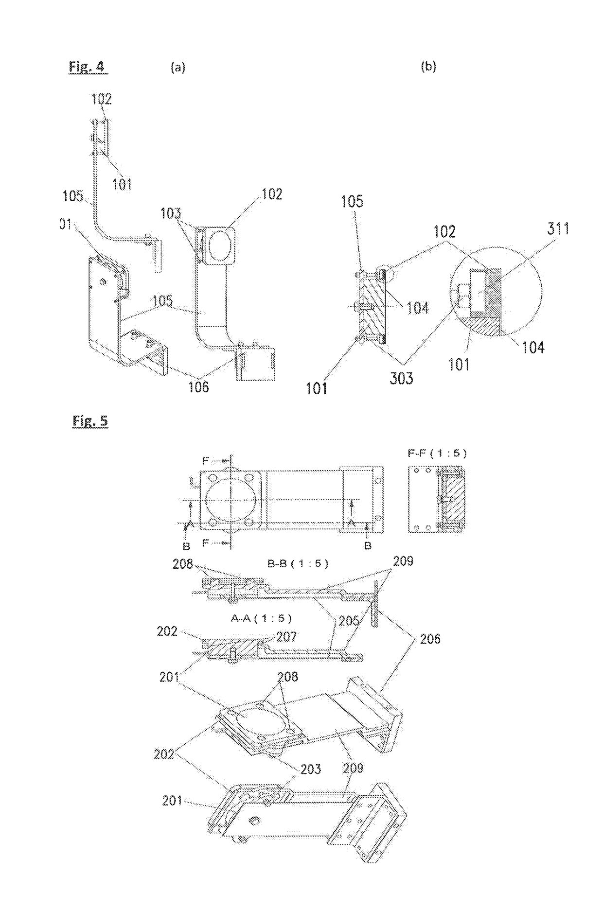
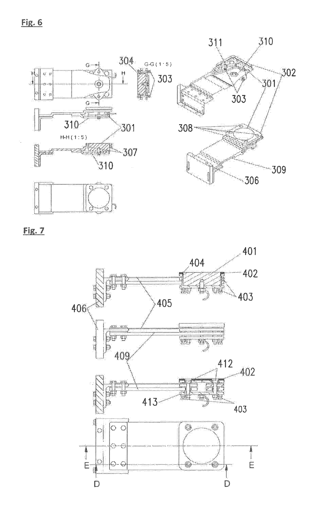
[0110]FIGS. 1 to 3 show a vibration absorber for a tower, in particular of a wind turbine, which is fitted, for example, with three electromagnetic brake devices (100, 200). These brake devices essentially consist of a retention device with a leaf spring, on one end of which a current-regulatable electromagnet is mounted. The mounting here is of the type that, with the current flowing, the electromagnet is pulled onto the metallic outside wall of the absorber mass (1) or a metallic contact surface (3), and at the same time tensions the leaf spring (105. 2015) attached thereto. The positioning of the electromagnet against the absorber mass or a contact surface which is connected to the absorber mass brakes the pendulum movement of the absorber mass if desired, until it stops. Variable current management (variation of the magnet strength by changing the current flow) calculated in advance enables specific influencing of the swinging of the pendulum and thus damping of the system to be...


PUM


Abstract

A vibration absorber which, in the broadest sense, is based on a pendulum device for dampening undesirable vibrations which occur in a very slender structure, such as a wind turbine. The undesirable vibrations are caused by an acting force, in particular wind force. The invention thereby relates to vibration absorbers in which the pendulum mass can be temporarily stopped or braked, either entirely or partially, by an electromagnetic brake. The power supply or the current regulation of the electromagnetic brake correspondingly controls the braking function of the electromagnetic brake.

Description

[0001]This application is a national stage completion of PCT / EP2017 / 000016 filed Jan. 9, 2017 which claims priority from European Application Serial No. 16 000 097.2 filed Jan. 15, 2016.FIELD OF THE INVENTION[0002]The invention relates to a vibration absorber which is based in the broadest sense on a pendulum device for damping undesired vibrations which occur due to forces acting, in particular wind forces in tall slim structures, in particular wind turbines. The invention here relates to vibration absorbers in which the pendulum mass can be completely or partially or temporarily stopped or braked by an electromagnetic brake, depending on control of the brake, by corresponding supply of current or current regulation. In a particularly advantageous embodiment, the vibration absorber is a rolling pendulum absorber.BACKGROUND OF THE INVENTION[0003]There are in principle various use cases of brakes for vibration absorbers. This applies both to vibration absorbers in wind turbines, but ...

Claims


Application Information

Patent Timeline
Patent Type & Authority Applications(United States)
IPC IPC(8): F01D25/04F03D80/80F03D7/02F16F7/10H02K49/04
CPCF01D25/04F03D80/82F03D7/0244F16F7/1011H02K49/046F05B2260/964F05B2260/903F16F2222/08F16F2230/18F16F2228/066Y02E10/72
Inventor MITSCH, FRANZ
Owner FM ENERGIE GMBH& CO KG
Why Eureka
Try Eureka