

Spatial Control of the Optical Focusing Properties of Photonic Nanojets
a technology of photonic nanojets and optical focusing properties, which is applied in the field of spatial control of the optical focusing properties of photonic nanojets, can solve the problems of limiting the application of their inherent properties, limiting the detection of deeply embedded nanostructures within cells, and no complete theoretical model has been adduced that can fully explain the observed super-resolution capability of microspheres
- Summary
- Abstract
- Description
- Claims
- Application Information
AI Technical Summary
Benefits of technology
Problems solved by technology
Method used
Image

Examples
Embodiment Construction
[0016]In accordance with embodiments of the invention, methods and apparatus are provided for concentrating light characterized by a central wavelength into a specified focal volume. In one embodiment, the method couples incident light through a plurality of successive transmissive asymmetric microstructure elements.
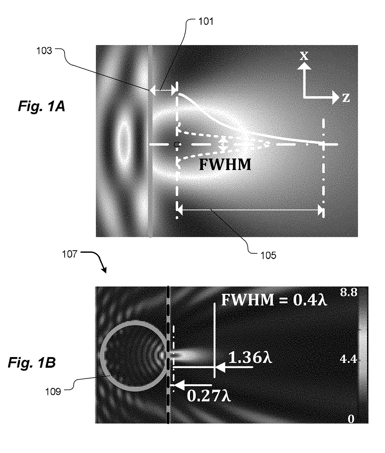
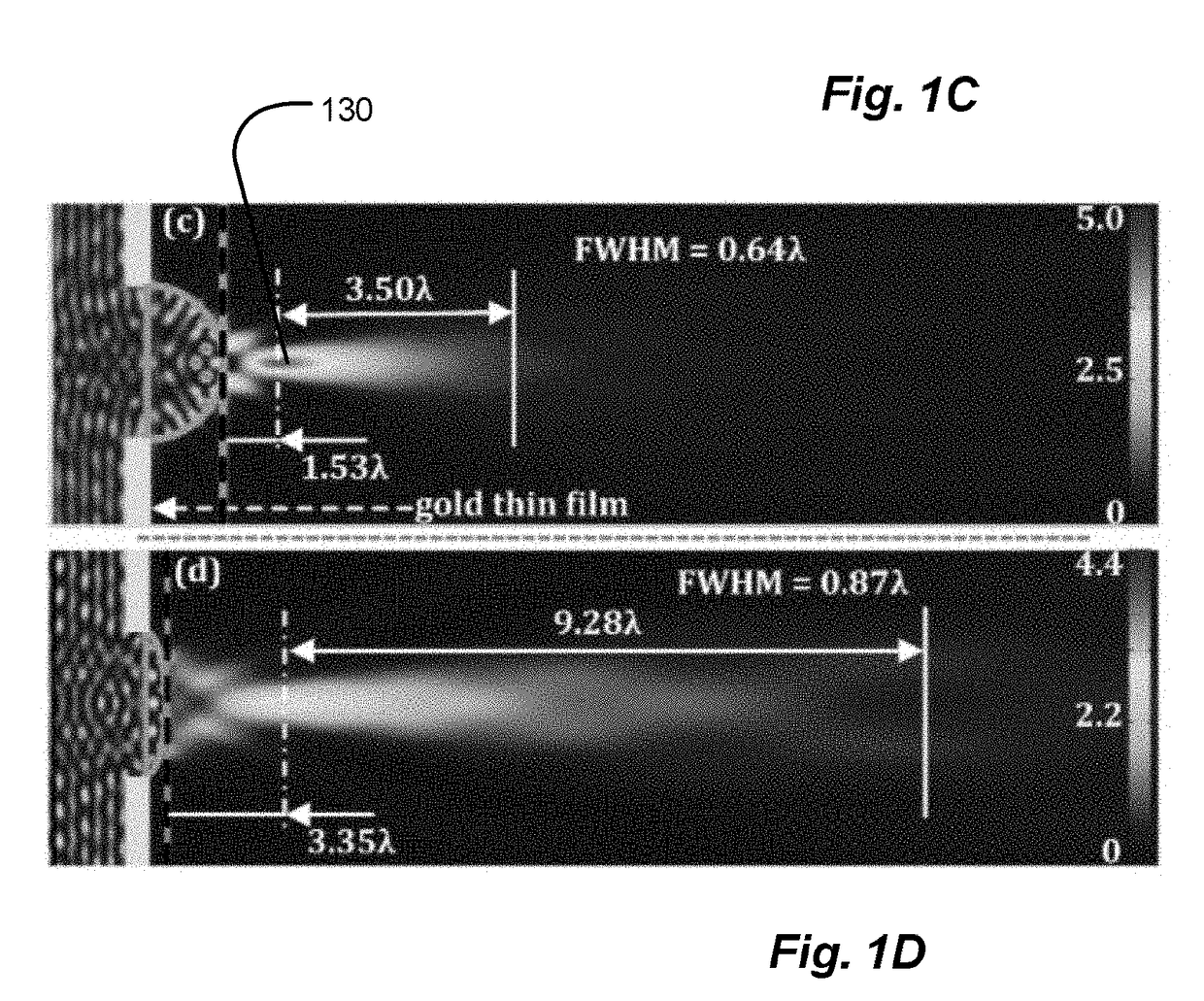
[0017]In other embodiments of the invention, the specified focal volume may be characterized by a waist having an intensity FWHM smaller than half the central wavelength of the incident light. Each of the plurality of successive transmissive asymmetric microstructure elements lacks any symmetry other than about a central propagation vector of the incident light. Each of the successive elements of the microstructure may be characterized by an index of refraction exceeding that of an ambient medium.
[0018]In accordance with further embodiments of the present invention, one of the plurality of successive transmissive asymmetric microstructure elements has a hemispherical cap...
PUM
 Abstract
Description
Claims
Application Information