Battery module and battery device
- Summary
- Abstract
- Description
- Claims
- Application Information
AI Technical Summary
Benefits of technology
Problems solved by technology
Method used
Image

Examples
Embodiment Construction
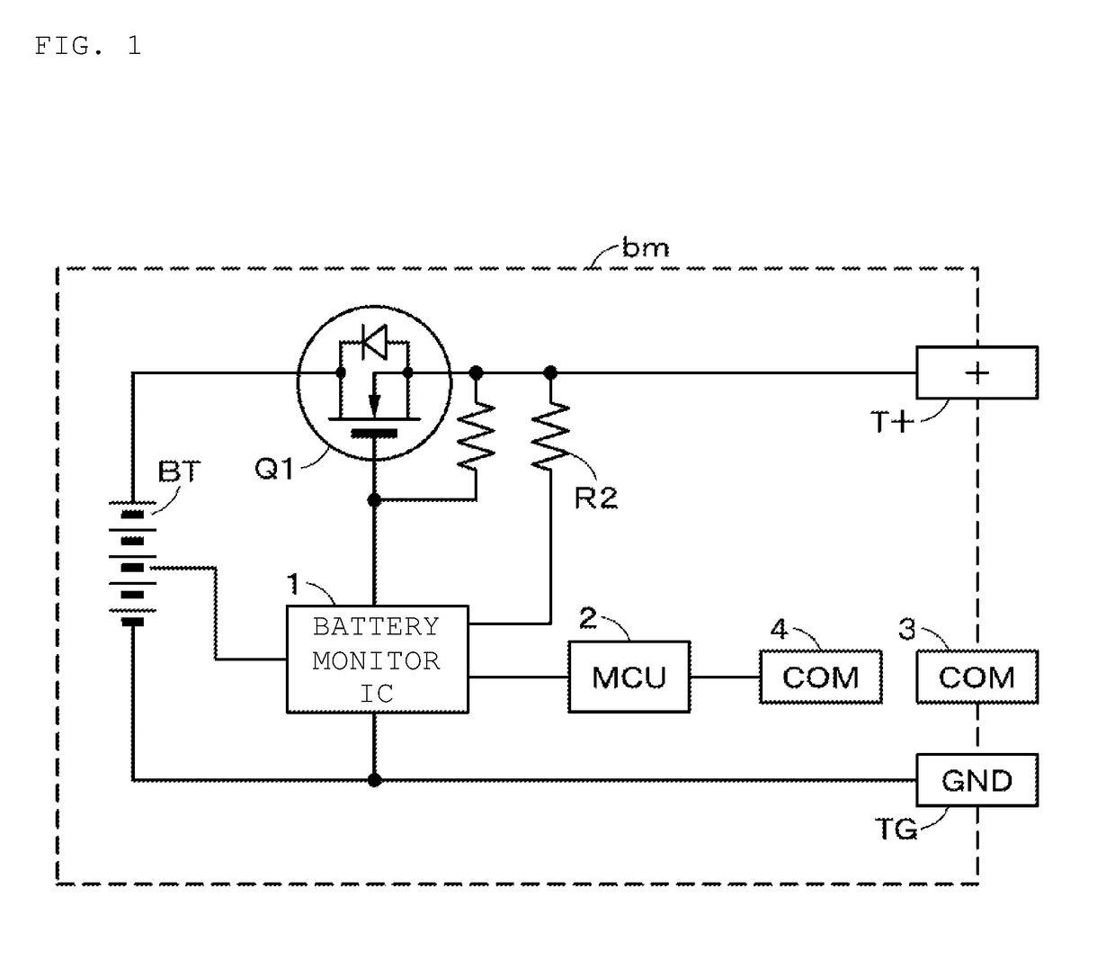
[0045]Prior to describing the embodiment of the present technology, the conventional problems will be described. FIG. 1 shows a configuration of a conventional battery module bm. The+side of the battery part BT in which a plurality of battery cells are connected in series is led out as the positive output terminal T+ through the drain-source path of the N-channel MOSFET (Q1). That is, the FET (Q1) is connected to the high side. A power MOSFET capable of a large current is used as the FET (Q1). The negative (−) side of the battery part BT is led out as the negative output terminal TG. The FET (Q1) has the function of a discharge load switch. An N-channel MOSFET is connected between the FET (Q1) and the+side of the battery part BT, as a charge load switch, so that the drain-source path is opposite to that of the FET (Q1), but for simplicity the FET is omitted. The battery part BT is not limited to a configuration in which a plurality of battery cells are connected in series, but may b...
PUM
 Abstract
Description
Claims
Application Information
 - R&D Engineer
- R&D Manager
- IP Professional
- Industry Leading Data Capabilities
- Powerful AI technology
- Patent DNA Extraction
Browse by: Latest US Patents, China's latest patents, Technical Efficacy Thesaurus, Application Domain, Technology Topic.
© 2024 PatSnap. All rights reserved.Legal|Privacy policy|Modern Slavery Act Transparency Statement|Sitemap