Reverse memory cell

a memory cell and reverse memory technology, applied in the field of memory devices, can solve the problems of complex processing of the lue device, design and programming of erasing operations, and the limitation of the use of the p-channel memory cell, and achieve the effect of reducing the complexity of the device, and reducing the cost of the devi

a memory cell and reverse memory technology, applied in the field of memory devices, can solve the problems of complex processing of the lue device, design and programming of erasing operations, and the limitation of the use of the p-channel memory cell, and achieve the effect of reducing the complexity of the device, and reducing the cost of the devi

US20190157296A1Active Publication Date: 2019-05-23SUNRISE MEMORY CORP

Image

  • Reverse memory cell
  • Reverse memory cell
  • Reverse memory cell

Examples


Embodiment Construction

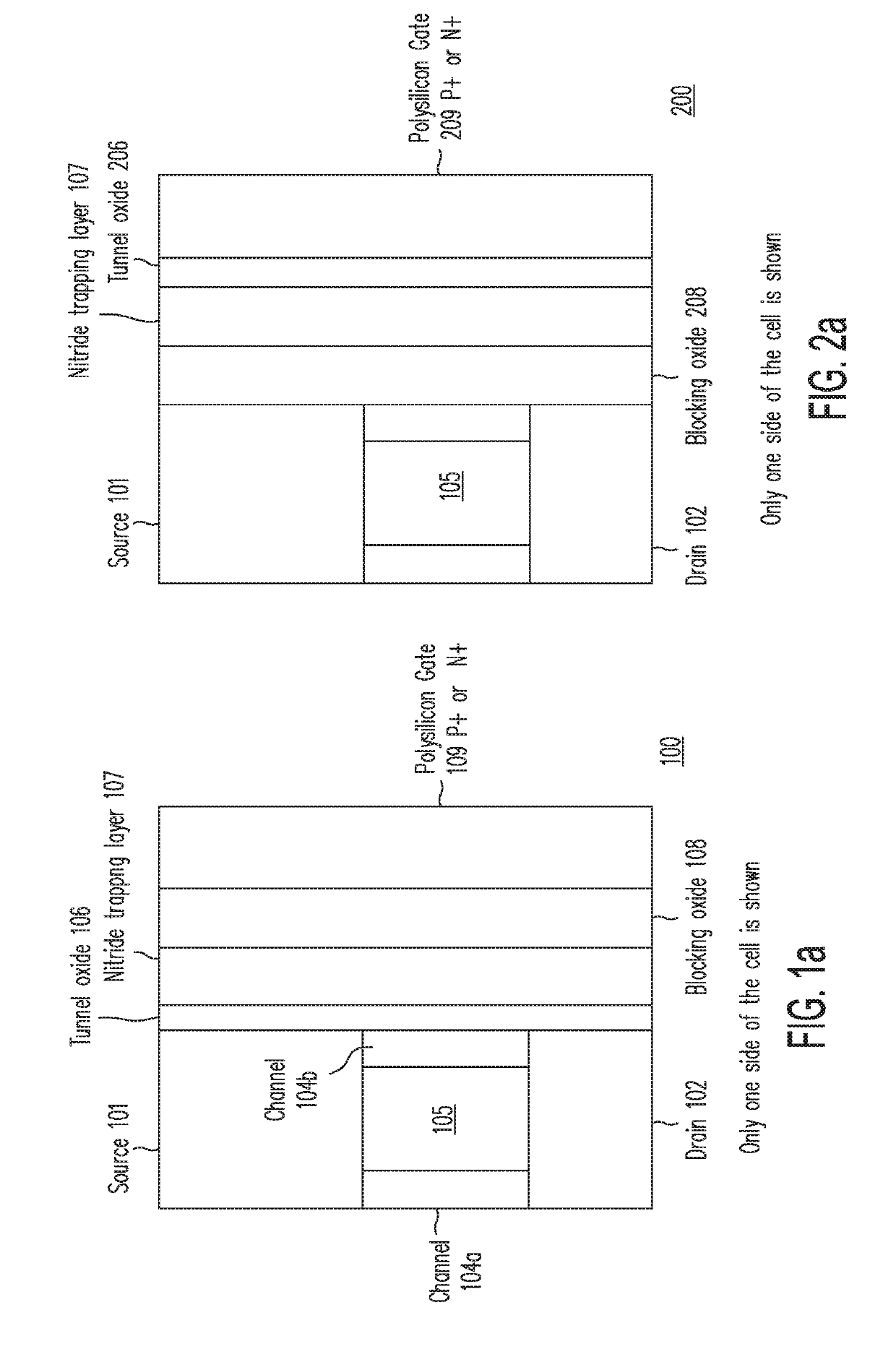
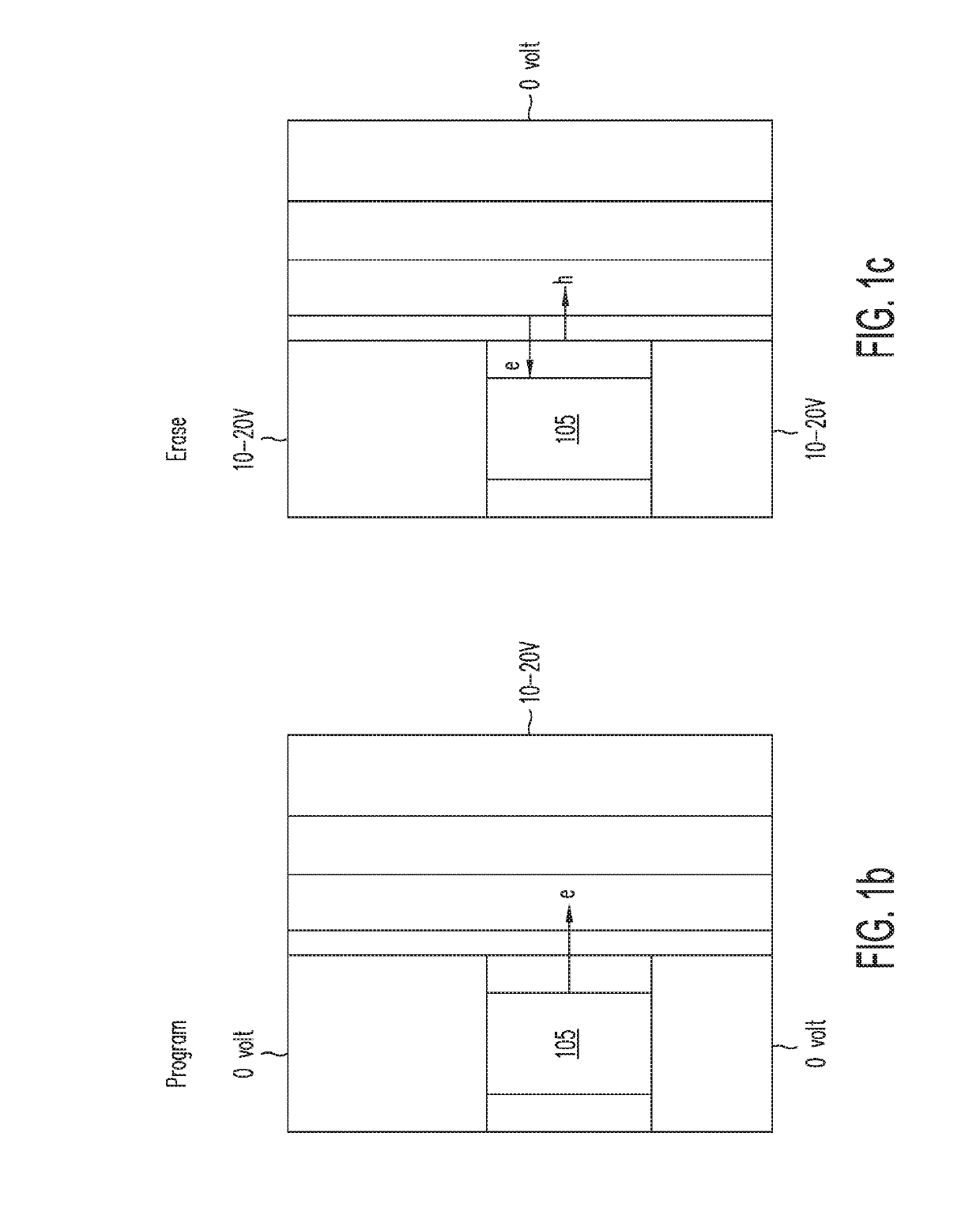
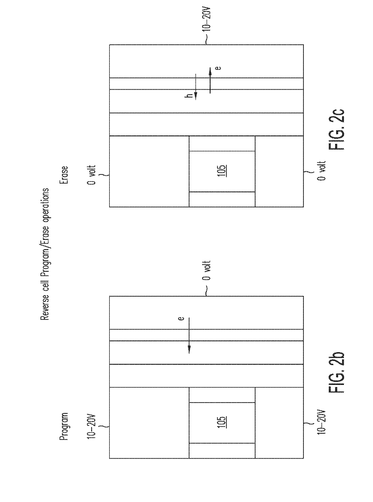
[0015]The present invention provides a non-volatile “reverse memory cell” for a 3-dimensional memory array. In this detailed description, the term “reverse memory cell” refers to a memory cell that includes a charge-trapping layer which is programmed or charged through gate-injection, rather than channel-injection. A reverse memory cell of the present invention may be implemented as either an n-channel memory cell or a p-channel memory cell, without incurring design or process penalties, or any complexity in programming or erase operations. Furthermore, all reading, programming, erase, program-inhibiting operations may be carried out in the reverse memory cell of the present invention using only one polarity of voltages: i.e., only positive voltages for an N-channel reverse memory cell and only negative voltages for P-channel reverse memory cell, thereby simplifying both the design and the power management operations.

[0016]The Non-provisional Patent Application, incorporated by refe...


PUM


Abstract

A non-volatile “reverse memory cell” suitable for use as a building block for a 3-dimensional memory array includes a charge-trapping layer which is programmed or charged through gate-injection, rather than channel-injection. Such a reverse cell may be implemented as either an n-channel memory cell or a p-channel memory cell, without incurring design or process penalties, or any complexity in programming or erase operations. Furthermore, all reading, programming, erase, program-inhibiting operations may be carried out in the reverse memory cell using only positive or only negative voltages, thereby simplifying both the design and the power management operations.

Description

CROSS-REFERENCE TO RELATED APPLICATIONS[0001]The present application relates to and claims priority of U.S. provisional patent application (“Provisional Application”), Ser. No. 62 / 588,097, entitled “REVERSE MEMORY CELL,” filed on Nov. 17, 2017. The present application relates also to U.S. patent application (“Non-provisional Patent Application”), Ser. No. 15 / 248,420, entitled “Capacitive-coupled Non-Volatile Thin-film Transistor Strings in Three-Dimensional Arrays,” filed on Aug. 29, 2016. The disclosures of the Provisional Application and the Non-provisional Patent Application are hereby incorporated by reference in their entireties.BACKGROUND OF THE INVENTION1. Field of the Invention[0002]The present invention relates to memory devices. In particular, the present invention relates to a memory device with a gate-injected charge storage layer.2. Discussion of the Related Art[0003]Memory devices with a gate-injected charge-storage layer have been disclosed, for example, in the articl...

Claims


Application Information

Patent Timeline
23 May 2019
Publication
US20190157296A1
IPC
H01L27/11582; H01L29/49; H01L29/423; H10B43/27
CPC
H01L27/11582; H01L29/4925; H01L29/42384; H01L29/4908; H01L29/792; H01L29/40117; G11C16/0466; G11C2216/28
Inventors
HARARI, ELI; SAMACHISA, GEORGE