
Apparatus for increase field of view for lidar detector and illuminator

a lidar detector and illuminator technology, applied in the direction of optical radiation measurement, instruments, using reradiation, etc., to achieve the effect of increasing customer satisfaction

Inactive Publication Date: 2019-01-31
GM GLOBAL TECH OPERATIONS LLC
View PDF6 Cites 1 Cited by
  • Summary
  • Abstract
  • Description
  • Claims
  • Application Information

AI Technical Summary

Benefits of technology

The present patent provides a way to verify the control commands of an autonomous vehicle, which can help identify software or hardware issues in the main control system. This makes the system more robust and reliable, improving customer satisfaction.

Problems solved by technology

However, fixed LiDAR systems typically require a large number of laser transmitters and detectors to achieve an acceptable density point cloud.

Method used


Image

  • Apparatus for increase field of view for lidar detector and illuminator
  • Apparatus for increase field of view for lidar detector and illuminator
  • Apparatus for increase field of view for lidar detector and illuminator

Examples


Embodiment Construction

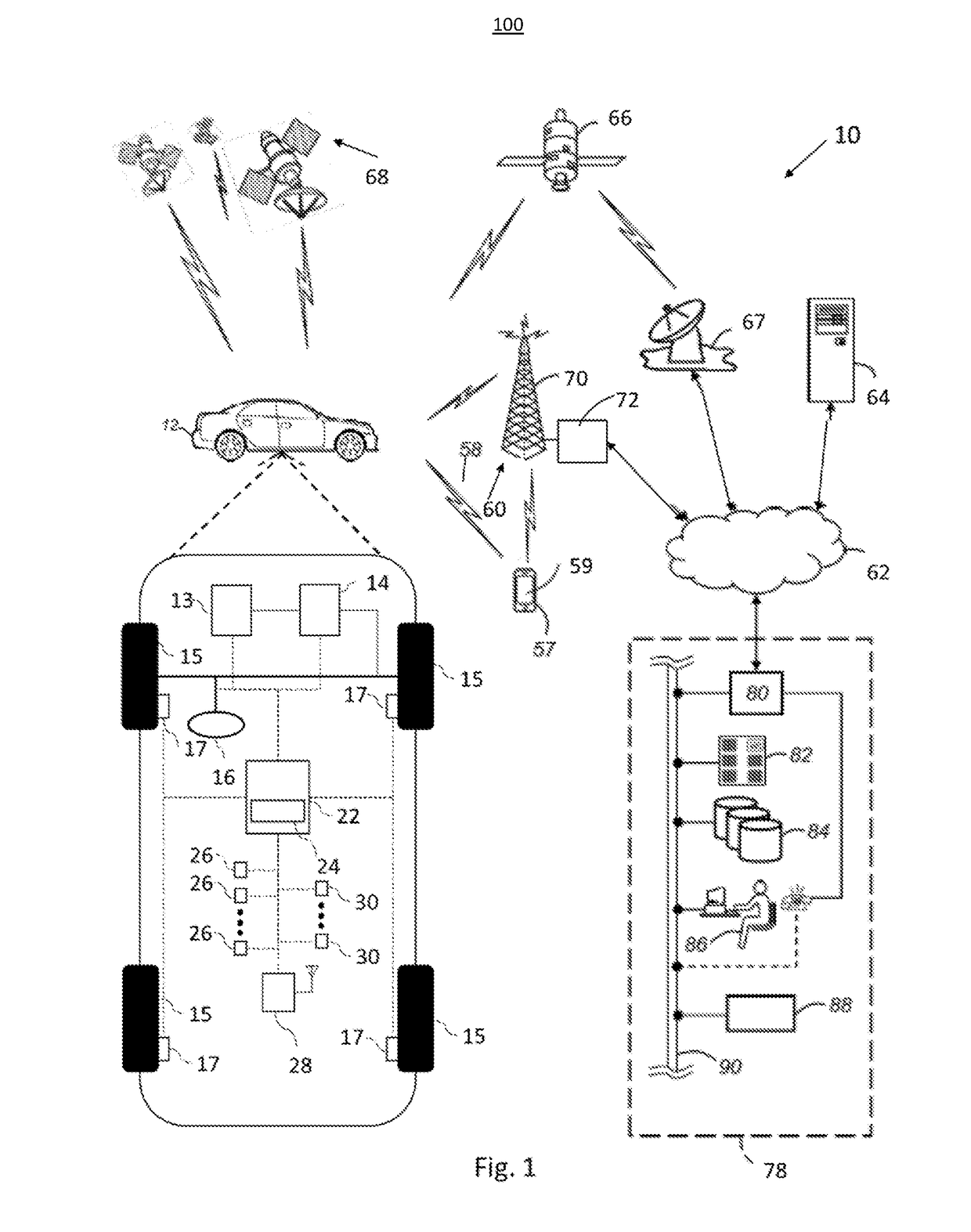
[0017]The following detailed description is merely exemplary in nature and is not intended to limit the disclosure or the application and uses thereof. Furthermore, there is no intention to be bound by any theory presented in the preceding background or the following detailed description. For example, the LiDAR sensor of the present invention has particular application for use on a vehicle. However, as will be appreciated by those skilled in the art, the LiDAR sensor of the invention may have other applications.

[0018]Modern vehicles sometimes include various active safety and control systems, such as collision avoidance systems, adaptive cruise control systems, lane keeping systems, lane centering systems, etc., where vehicle technology is moving towards semi-autonomous and fully autonomous driven vehicles. For example, collision avoidance systems are known in the art that provide automatic vehicle control, such as braking, if a potential or imminent collision with another vehicle o...


PUM


Abstract

The present application generally relates communications and hazard avoidance within a monitored driving environment. More specifically, the application teaches a system for improved target object detection in a vehicle equipped with a laser detection and ranging LiDAR system by using a double convex lens or a spherical lens in order of realize a greater field of view for a LiDAR detector array.

Description

BACKGROUND[0001]The present application generally relates to autonomous and semiautonomous vehicles. More specifically, the application teaches an apparatus for improved target object detection in a vehicle equipped with a laser detection and ranging LIDAR system.Background Information[0002]The operation of modern vehicles is becoming more automated, i.e. able to provide driving control with less and less driver intervention. Vehicle automation has been categorized into numerical levels ranging from zero, corresponding to no automation with full human control, to five, corresponding to full automation with no human control. Various automated driver-assistance systems, such as cruise control, adaptive cruise control, and parking assistance systems correspond to lower automation levels, while true “driverless” vehicles correspond to higher automation levels.[0003]Increasingly, vehicles being equipped to determine the environment around them autonomously or semiautonomous using onboard...

Claims


Application Information

Patent Timeline
IPC IPC(8): G01S17/89G01S7/481G01J1/04G01S17/931
CPCG01S17/89G01J1/0411G01S7/4815G01S7/481G05D1/0219G01S17/931G01J1/0219G01J1/4228G01S17/42G01S7/4816
Inventor LIPSON, ARIEL
Owner GM GLOBAL TECH OPERATIONS LLC
Learn More