Air File

a technology of air file and air cavity, which is applied in the field of hand tools, can solve the problems of energy waste, complex structure of conventional reciprocating file, etc., and achieve the effect of reducing energy consumption and simple structur

Inactive Publication Date: 2019-02-07
LIAW JIAN SHIOU
View PDF7 Cites 3 Cited by
  • Summary
  • Abstract
  • Description
  • Claims
  • Application Information

AI Technical Summary

Benefits of technology

[0006]The main objective of the present invention is to provide an air file with a simple structure and may reduce energy consumption.

Problems solved by technology

However, the conventional reciprocating file has complex structures.
The power supplied by the motor is consumed gradually during the transmission and causes a problem of energy waste.

Method used


Image

  • Air File
  • Air File
  • Air File

Examples


Embodiment Construction

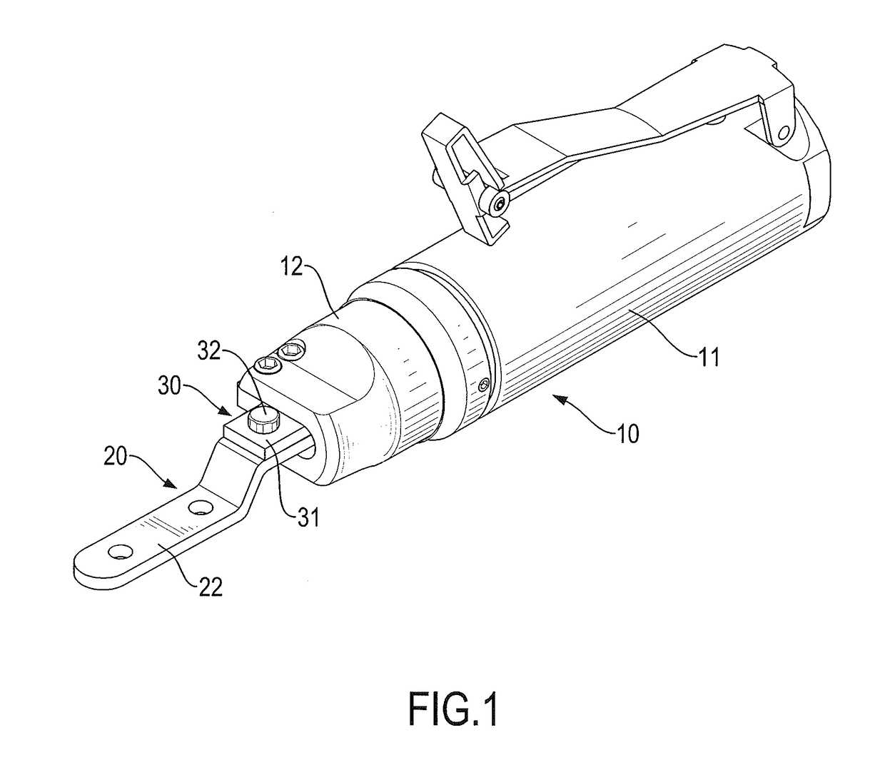
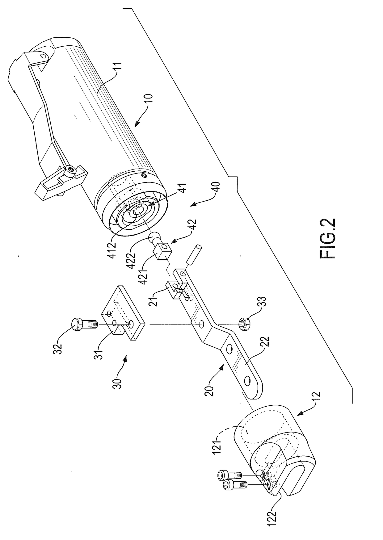
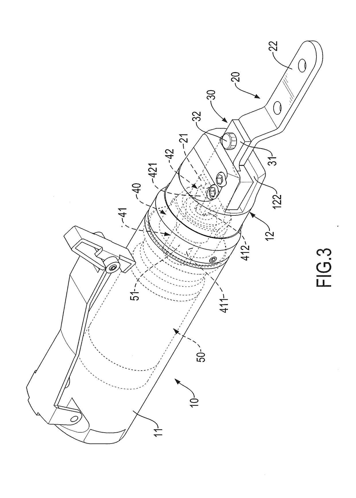
[0015]With reference to FIGS. 1 and 2, an air file in accordance with the present invention comprises a body 10, a fastening member 20, a pivoting assembly 30, and a driving assembly 40. The fastening member 20, the pivoting assembly 30, and the driving assembly 40 are assembled on the body 10.

[0016]With reference to FIGS. 1 and 2, the body 10 has a handle 11 and a front cover 12. The handle 11 is hollow, and a driving device 50 is mounted inside the handle 11. The driving device 50 may be an electric motor or a pneumatic rotor. The front cover 12 has a first end, a second end, a receiving hole 121, and a receiving recess 122. The first end and the second end of the front cover 12 are opposite each other. The receiving hole 121 extends from the first end of the front cover 12 toward the second end of the front cover 12. The receiving recess 122 has a cross-section in an elongated shape. The receiving recess 122 extends from the second end of the front cover 12 toward the first end o...


PUM

PropertyMeasurementUnit
energyaaaaaaaaaa
poweraaaaaaaaaa
energy consumptionaaaaaaaaaa

Abstract

An air file has a body, a fastening member, and a driving assembly. The body has a handle and a front cover connected to the handle. The fastening member is swingably assembled to the front cover and has a pivoting end and a connecting end. The pivoting end of the fastening member is inserted inside the front cover. The connecting end of the fastening member extends out of the front cover. The driving assembly is mounted inside the body and has an eccentric shaft and a swinging unit. The eccentric shaft is connected to a driving device and has an eccentric hole facing to the front cover. The swinging unit has a pivoting portion and a ball joint. The pivoting portion is pivotally connected to the pivoting end of the fastening member. The ball joint is engaged in the eccentric hole of the eccentric shaft.

Description

BACKGROUND OF THE INVENTION1. Field of the Invention[0001]The present invention relates to a hand tool, and more particularly to an air file that has a simple structure and the advantage of energy conservation.2. Description of Related Art[0002]A file is a hand tool for polishing or grinding a workpiece with uneven surfaces or edges. A conventional reciprocating file has a motor, an eccentric component, a helical gear, a reciprocating shaft, and a tool holder. The motor has a driving shaft. The eccentric component has a first shaft and a second shaft. The first shaft and the second shaft of the eccentric component are eccentric and extend toward two opposite directions. The helical gear is mounted on and around the first shaft of the eccentric component and contacts a front end of the driving shaft of the motor. The helical gear is driven by the front end of the driving shaft of the motor. The helical gear and the first shaft are able to rotate simultaneously. The reciprocating shaf...

Claims


Application Information

Patent Timeline
Patent Type & Authority Applications(United States)
IPC IPC(8): B24B23/02B25D9/08B23D51/18
CPCB24B23/026B25D9/08B23D67/00B24B23/00B25D9/00B23D51/18B23D67/12B23D69/00B24B23/04B24B27/08B24B47/12B24B47/14
Inventor LIAW, JIAN-SHIOU
Owner LIAW JIAN SHIOU
Why Eureka
Try Eureka