Method for providing a fluid supply device and use thereof

Inactive Publication Date: 2019-02-14
KLINGELNBERG AG
View PDF16 Cites 5 Cited by
  • Summary
  • Abstract
  • Description
  • Claims
  • Application Information

AI Technical Summary

Problems solved by technology

It has been shown that the setting of the liquid agent supply 50 is not always optimal.
Under certain circumstances, the full effect therefore cannot be ac

Method used


Image

  • Method for providing a fluid supply device and use thereof
  • Method for providing a fluid supply device and use thereof
  • Method for providing a fluid supply device and use thereof

Examples


Embodiment Construction

[0050]Terms, which are also used in relevant publications and patents, are used in conjunction with the present description. However, it is to be noted that the use of these terms is merely to serve for better comprehension. The inventive concepts and the scope of protection of the patent claims are not to be restricted in the interpretation by the specific selection of the terms. The invention may be readily transferred to other term systems and / or technical fields. The terms are to be applied accordingly in other technical fields.

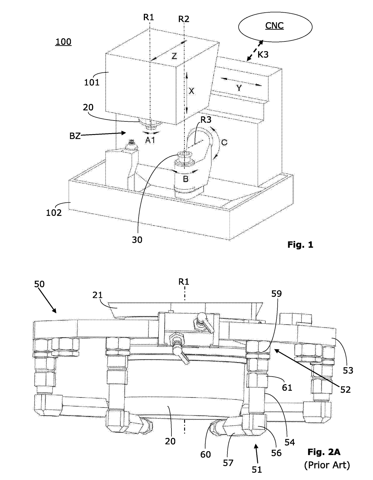
[0051]This relates here to the cooling and / or lubricating in conjunction with a chip-removing method for machining workpieces 30. In particular, the chip-removing method relates to the machining of metal workpieces 30, for example, gearwheels, shafts, clutch parts, and the like.

[0052]The method of the invention is especially designed for use in the environment of a machine tool 100, in which a component / workpiece 30 is machined by removing chips. An exemp...


PUM


Abstract

Method for providing a fluid feeding device, which is designed specifically for use in a machining zone of a machine tool in order to deliver a fluid in the direction of an area of interaction between a tool and a workpiece, comprising the following steps: a. computer-aided definition of the 3-dimensional configuration of the machining zone, taking into account the workpiece and the tool that is to be used for machining the workpiece in the machining zone of the machine tool, b. computer-aided definition of the 3-dimensional form and the position of at least one specifically adapted outlet nozzle (251) of the fluid feeding device, with the inclusion of information that was defined in step a., c. provision of a data record that describes the 3-dimensional form of this outlet nozzle (251), d. use of the data record to produce this outlet nozzle (251) by means of a numerically controlled production process (200).

Description

[0001]The present invention relates to methods for providing a fluid supply device, which is capable of cooling and / or lubricating components / workpieces during or after cutting machining. Moreover, it relates to the use of a fluid supply device.[0002]The priority of patent application DE 10 2016 103 202.6 is claimed, which was filed on 24 Feb. 2016 in the name of the present applicant with the German Patent and Trademark Office.PRIOR ART[0003]Using a coolant or lubricant during cutting (metal) machining (for example, during gear tooth grinding) is known. Present machine tools and machining centers (for example, the bevel gear machine tool 100 shown in FIG. 1) are therefore often equipped with a high-performance liquid agent supply 50. Details of a conventional fluid supply device 50, which comprises multiple rigidly constructed outlet nozzles 51, are shown in FIGS. 2A and 2B.[0004]A gooseneck-type head is usually assembled and set manually such that the liquid jet which exits from t...

Claims


Application Information

Patent Timeline
IPC IPC(8): G05B19/4099B23Q11/10
CPCG05B19/4099B23Q11/1076G05B2219/49023G05B2219/35079B33Y50/02B33Y80/00B29C64/393
Inventor SCHALASTER, ROLF
Owner KLINGELNBERG AG
Why Eureka
Try Eureka