
Scene Flow Camera

Inactive Publication Date: 2019-02-14
KIRBY COMPANY
View PDF3 Cites 5 Cited by
  • Summary
  • Abstract
  • Description
  • Claims
  • Application Information

AI Technical Summary

Benefits of technology

This patent describes a camera rig that uses optical flow fields to align image sequences from different sensors. This allows for more accurate depth and scene flow estimation, and enables the production of dense depth maps and 3D scene flow through a tube. This method overcomes the problem of previous methods that use visual similarity to align images. The technical effects of this patent include improved accuracy and flexibility in image alignment and 3D imaging.

Problems solved by technology

This methodology, however, is prone to errors inherent in all correspondence finding algorithms, namely that finding accurate correspondences rely on the use of visual similarity in the pairs of images to match corresponding pixels.
While visual similarity measures produce good results in laboratory experiments, they often fail in real world situations where the lighting for the cameras at different poses is not identical (a common situation in real world imaging where surfaces reflect different amounts of light in different directions), where the cameras image different frequencies of light (a desirable situation in robotics, autonomous vehicles and surveillance where there are significant benefit for using a combination of visible light and infrared light) or where the camera images are noisy (common in low light conditions).

Method used


Image

  • Scene Flow Camera
  • Scene Flow Camera
  • Scene Flow Camera

Examples


Embodiment Construction

FIGS. 1-2—Preferred Embodiment

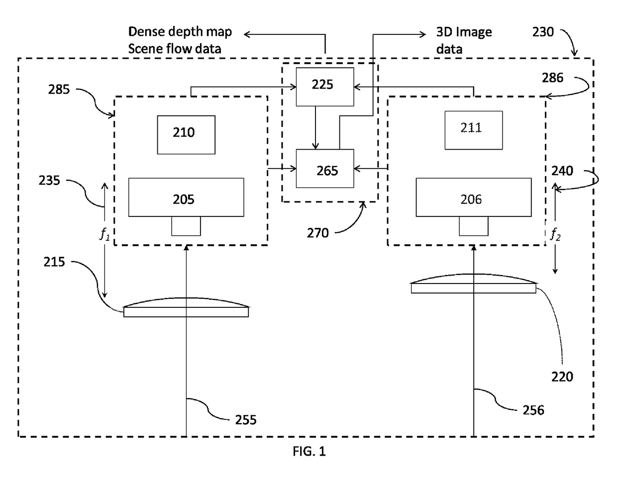
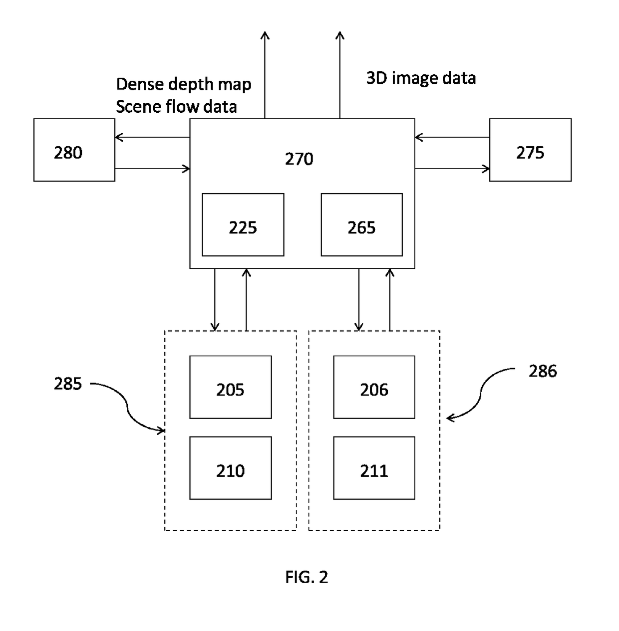
[0077]FIG. 1 is a schematic representation showing the optical system, imaging system and image processing system of a preferred embodiment of the scene flow camera. A first optical flow sensor imaging first range of light frequencies 285 comprised of a first image sensor, imaging first light frequency range 205 and a first optical flow processor 210, image along an optical axis of first image sensor 255 via a first imaging lens 215 having a first focal length 235. A second optical flow sensor imaging second range of light frequencies 286 comprised of a second image sensor, imaging second light frequency range 206 and a second optical flow processor 211, image along an optical axis of second image sensor 256 via a second imaging lens 220 having a second focal length 240. The image formed in the first image sensor, imaging first range of light frequencies 205 having a partial overlap with the image formed in the second image sensor, imaging a second ligh...


PUM


Abstract

A method and system for acquiring dense 3D depth maps and scene flow using a plurality of image sensors, each image sensor associated with an optical flow processor, the optical flow fields being aligned to find dense image correspondences. The disparity and / or ratio of detected optical flows in corresponding pixels combined with the parameters of the two optical paths and the baseline between the image sensors is used to compute dense depth maps and scene flow.

Description

CROSS-REFERENCE TO RELATED APPLICATIONS[0001]This application claims the benefit of U.S. provisional applications No. 62 / 374,998 filed 15 Aug. 2016 and No. 62 / 411,837, filed 24 Oct. 2017.FEDERALLY SPONSORED RESEARCH[0002]Not applicable.SEQUENCE LISTING OR PROGRAM[0003]Not applicable.BACKGROUND OF THE INVENTIONField of Invention[0004]This invention relates to an optical apparatus for the measurement of scene flow and more particularly to an optical apparatus which combines optical flow images acquired at two different image sensor poses and aligns the optical flow fields to estimate the scene flow (structure and motion) of the 3D scene.Prior Art[0005]Scene flow is the dense or semi-dense 3D motion field of a scene with respect to an observer. Applications of scene flow are numerous, including autonomous navigation in robotics, manipulation of objects in dynamic environments where the motion of surrounding objects needs to be predicted, improved Visual Odometry (VO) and Simultaneous L...

Claims


Application Information

Patent Timeline
IPC IPC(8): G06T7/285G06T7/593H04N13/02G06T7/38
CPCG06T7/285G06T7/593G06T7/38H04N13/271G06T2207/10024G06T2207/10028G06T2207/10048G06T2207/10021H04N2013/0081H04N13/239G06T7/269G06T7/579
Inventor KIRBY, RICHARD
Owner KIRBY COMPANY
Features
  • Generate Ideas
  • Intellectual Property
  • Life Sciences
  • Materials
  • Tech Scout
  • Unparalleled Data Quality
  • Higher Quality Content
  • 60% Fewer Hallucinations
Learn More