Projection apparatus, control method, and storage medium

a technology of projection apparatus and control method, applied in the field of projection, can solve the problems of general undesirable image quality, inability to correct luminance level difference between overlap regions, and inability to lower the luminance of overlap regions, so as to achieve the effect of suppressing contrast deterioration

Active Publication Date: 2019-02-14
CANON KK
View PDF8 Cites 5 Cited by
  • Summary
  • Abstract
  • Description
  • Claims
  • Application Information

AI Technical Summary

Benefits of technology

[0009]The present disclosure addresses these areas by providing a projection apparatus that can simply suppress black floating in an overlap region while suppressing deterioration of contrast.

Problems solved by technology

However, in this method, it is not possible to correct a luminance level difference between an overlap region and a non-overlap region when black displays are overlapped.
However, an input signal of the black display portion is 0, so that it is not possible to lower the luminance of the overlap region and match the luminance of the overlap region and the non-overlap region.
When the contrast is degraded, sharpness of an image is also degraded, so that the quality of the image generally becomes undesirable.
Further, in Japanese Patent Laid-Open No. 2001-268476, a user manually sets a region to be shielded from light while viewing a screen, so that the operation of the user is troublesome.

Method used


Image

  • Projection apparatus, control method, and storage medium
  • Projection apparatus, control method, and storage medium
  • Projection apparatus, control method, and storage medium

Examples


first embodiment

Outline of First Embodiment

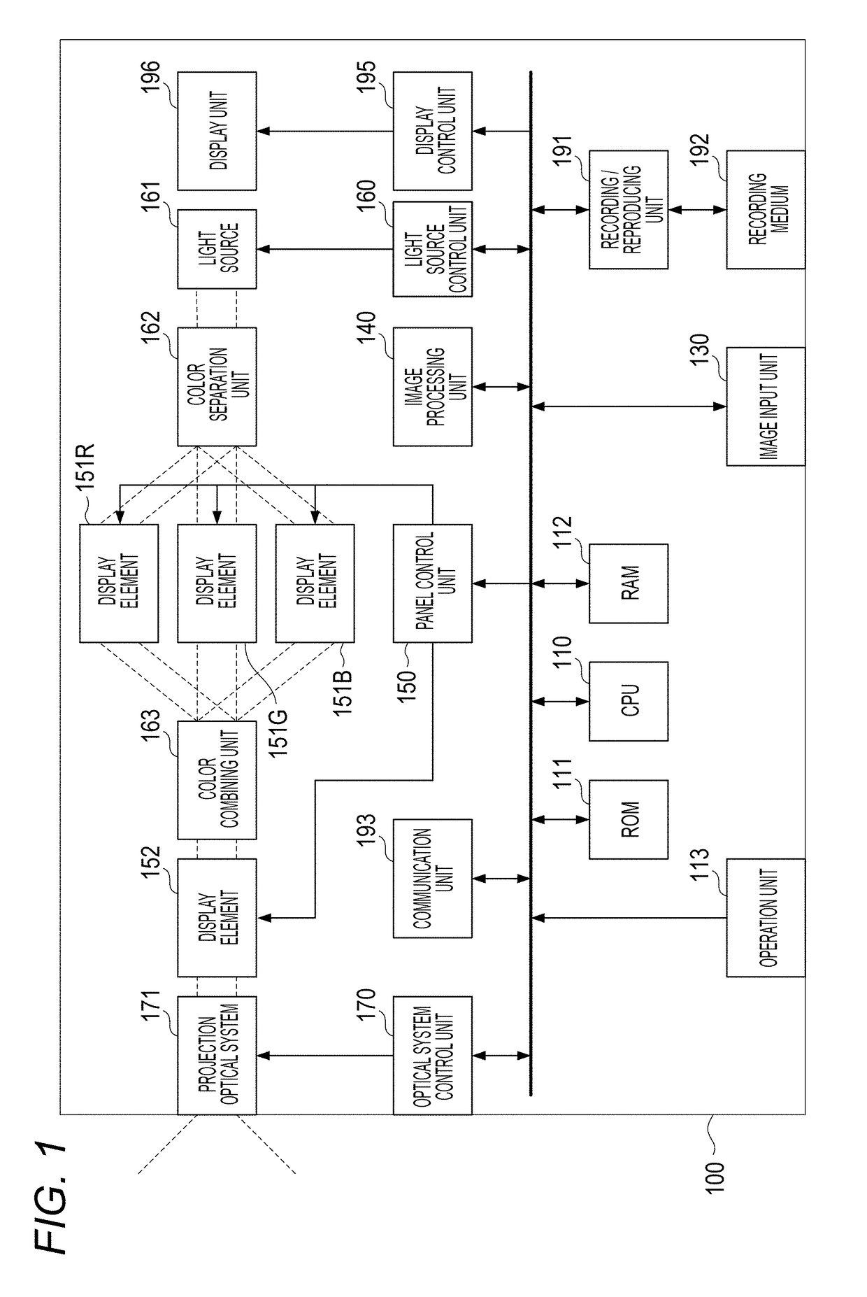
[0041]FIG. 1 is a diagram showing a configuration of a projector 100. The projector 100 of the present embodiment has a central processing unit (CPU) 110, a read only memory (ROM) 111, a random access memory (RAM) 112, an operation unit 113, an image input unit 130, an image processing unit 140, a panel control unit 150, display elements (151R, 151G, and 151B), and a display element 152. Further, the projector 100 has a light source 161, a light source control unit 160, a color separation unit 162, a color combining unit 163, an optical system control unit 170, a projection optical system 171, a recording / reproducing unit 191, a recording medium 192, a communication unit 193, a display control unit 195, and a display unit 196.

[0042]The CPU 110, which may include one or more processors and one or more memories, may control each operation block of the projector 100 by using a program stored in the ROM 111 described later. The CPU 110 controls each operation ...

second embodiment

[0150]In the present embodiment, a projector will be described in the same manner as in the first embodiment.

[0151]In the present embodiment, a case will be described where the display element 151 of the projector 100 is a time modulation panel. In the same manner as in the first embodiment, the display element 151 represents gradation in a temporal direction by a PWM pattern by using a digital signal. However, a liquid crystal element is used instead of DMD.

[0152]In the case of a liquid crystal element that operates with a PWM drive system, a specific image quality disturbance occurs in a gradation pattern for edge blending.

[0153]In the present embodiment, a principle of generation of the image quality disturbance and suppression of the image quality disturbance by the present disclosure will be described.

[0154]The configuration and the basic operation of the projector 100 other than the premises described above are the same as those of the first embodiment, so that the description...

third embodiment

[0170]In the present embodiment, a projector will be described in the same manner as in the first and the second embodiments.

[0171]In the present embodiment, a case will be described where the display element 151 of the projector 100 is an amplitude modulation type liquid crystal panel and the display element 152 is a time modulation type DMD.

[0172]The configuration and the basic operation of the projector other than the premises described above are the same as those of the first and the second embodiments, so that the description thereof will be omitted.

[0173]A phenomenon that the light source light outputted from the light source 161 is modulated and becomes projection light having a desired luminance in the present embodiment will be described with reference to a time chart in FIG. 8.

[0174]FIG. 8 is a time chart when light of a pixel having a pixel value of 9 (the maximum pixel value is 15) of the image is reduced to 75% as the gradation processing and projection light of 6.75(=9...


PUM


Abstract

A projection apparatus that projects a projection image includes a first panel, a second panel, a projection optical system that projects light that has passed through the first panel and the second panel, an information acquisition unit that acquires light reduction information of a region which is a part of the projection image and overlaps with an image projected by another projection apparatus, and a panel control unit that controls the first panel based on data of the projection image and controls the second panel based on the light reduction information.

Description

BACKGROUNDField of the Disclosure[0001]The present disclosure generally relates to projection and, more particularly, to a projection apparatus, a control method of a projection apparatus, and a storage medium.Description of the Related Art[0002]A multiple projection system has been proposed which can project one large image by using a plurality of projectors and connecting together images projected from the projectors on a screen used as a projection surface.[0003]In the multiple projection system, a method is known which makes a luminance level difference between an overlap region and a non-overlap region inconspicuous by overlapping end portions of projection images and reducing / adjusting the luminance of the overlap region in order to make a connection portion between the projection images hardly visually recognized. This method is called edge blending processing. As a typical method, there is processing that gradually reduces luminance toward an end portion of a screen in an ov...

Claims


Application Information

Patent Timeline
Patent Type & Authority Applications(United States)
IPC IPC(8): H04N9/31
CPCH04N9/3182H04N9/3105H04N9/3123H04N9/3147H04N9/3185H04N9/3126H04N9/3188
Inventor IGUCHI, SHOTAYUI, HIDEAKI
Owner CANON KK
Why Eureka
Try Eureka