
Industrial cleaning installation with vapour condensation and related methods

a technology of industrial cleaning and condensation, applied in the direction of cleaning using liquids, separation processes, manufacturing tools, etc., can solve the problems of increasing complexity in terms of required equipment and maintenance procedures, affecting the life of industrial robots used in automated cleaning installations, and affecting the efficiency of cleaning operations, etc., to achieve the effect of simplifying maintenance and/or retrofitting operations

Inactive Publication Date: 2019-02-21
ELWEMA AUTOMOTIVE
View PDF0 Cites 4 Cited by
  • Summary
  • Abstract
  • Description
  • Claims
  • Application Information

AI Technical Summary

Benefits of technology

The patent describes a system that reduces the amount of air ducts needed and simplifies the maintenance of a vapor condenser in a handheld robot. By arranging the vapor condenser below the platform of the robot, the air flow is improved and directed away from the main areas of operation. This results in better fluid dynamics and reduces the amount of duct work needed. Additionally, the simplified maintenance makes it easier to keep the installation clean and functional.

Problems solved by technology

This atmosphere is known to be detrimental to the lifetime of robots typically used in automated cleaning installations.
As will be understood, industrial robots used in these kinds of installations are both expensive and sensitive pieces of equipment.
However, they increase complexity in terms of required equipment and maintenance procedures.

Method used


Image

  • Industrial cleaning installation with vapour condensation and related methods
  • Industrial cleaning installation with vapour condensation and related methods
  • Industrial cleaning installation with vapour condensation and related methods

Examples


Embodiment Construction

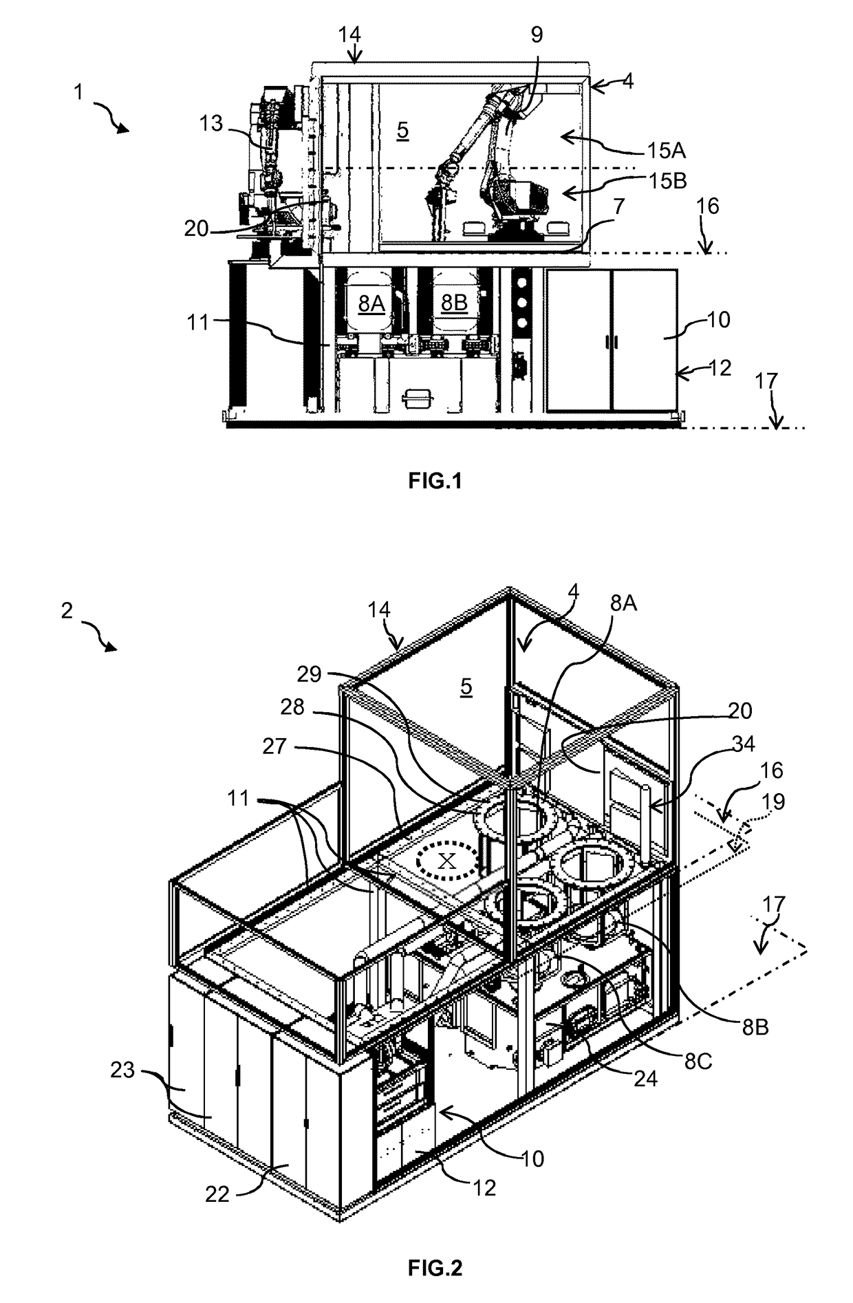
[0055]FIG. 1 shows a side elevation of the large side of an industrial cleaning installation 1. The cleaning installation 1 includes a housing 4 for an articulated industrial robot 9, e.g. a vertically articulated 6-DOF robot. A workspace 5 inside the housing 4 is enclosed, e.g. by four sidewalls, a roof and a platform 7 in suitable manner, a simple configuration being a rectangular cuboid. The sidewalls of the housing 4 can for example be configured according to German utility model DE 20 2013 101 377 U1. Generally, the housing 4 forms a substantially air-tight enclosure to contain the inner atmosphere of the workspace 5.

[0056]The cleaning installation 1 includes a number of processing receptacles 8A, 8B, 8C for performing various steps of a cleaning process in order to clean a machined metal part such as a cylinder block, a cylinder head or a crankshaft of an internal combustion engine (not shown). Suitable cleaning processes are known to the skilled person, and typically include ...


PUM


Abstract

An industrial installation and process are provided for cleaning workpieces, in particular engine components or transmission components. The installation has a housing enclosing a workspace and an industrial robot mounted inside the housing, in particular on a platform. An air recirculation device having a vapour condenser and ductwork with one or more intakes for admitting vapour-charged air from the workspace and one or more exits for returning dehumidified air to the workspace. The vapour condenser preferably includes a heat recovery unit. The vapour condenser is arranged at a level below the top of the housing, preferably below the platform and / or each of the one or more intakes is arranged at a level below the upper half of the workspace, preferably on or below the platform.

Description

TECHNICAL FIELD[0001]The present invention generally relates to the field of industrial cleaning of workpieces, and more specifically to cleaning installations and methods for machined metal parts, in particular components of automotive engines, e.g. cylinder blocks, cylinder heads, crankshafts or of transmission components, e.g. gearboxes.BACKGROUND ART[0002]In the field of concern, workpieces are typically cleaned by processes that involve a heated cleaning liquid, e.g. by flood-washing (German: Flutwaschen), high-pressure cleaning, high-pressure deburring and the like, as disclosed for instance in international patent application WO 2006 / 077 037 A1 or in German utility model DE 20 2013 100 959 U1.[0003]These processes typically create vapour and mist due to heat-induced evaporation and / or jets creating droplets, thereby creating a vapour-charged atmosphere. This atmosphere is known to be detrimental to the lifetime of robots typically used in automated cleaning installations. The...

Claims


Application Information

Patent Timeline
Patent Type & Authority Applications(United States)
IPC IPC(8): B08B15/02B08B3/02B08B3/10B01D53/26
CPCB08B15/02B08B3/024B08B3/10B01D53/265B08B2203/007B08B3/02B08B3/04B25J21/00Y02P70/10B25J11/00
Inventor ALVAREZ, ANTONIOSONNTAG, DIETMAR
Owner ELWEMA AUTOMOTIVE
Learn More