
Non-invasive radio-frequency ablation system

a radiofrequency ablation and non-invasive technology, applied in the field of non-invasive radiofrequency ablation systems, can solve the problems of reducing invasive rfa treatment techniques, and thermal damage to peripheral non-targeted tissue, so as to reduce the risk of treatment complications and eliminate bleeding or perforation

Inactive Publication Date: 2019-02-28
SU SEA QUAN
View PDF13 Cites 0 Cited by
  • Summary
  • Abstract
  • Description
  • Claims
  • Application Information

AI Technical Summary

Benefits of technology

The present invention provides a non-invasive radio-frequency ablation system that eliminates bleeding or perforation at the lesion position, reducing the risk of treatment complications. The system uses adjustable electrodes that allow for changing the treatment depth by regulating the distance between them. Additionally, a tissue contact cooling unit can lower the temperature of the contact tissue surface and increase the impedance of it, sparing it from thermal damage and enhancing the RF flow and thermal ablation effect at a deeper layer during treatment. Furthermore, the system may also have a temperature sensing unit and / or a treatment depth sensing unit to enhance the therapeutic effect.

Problems solved by technology

Although RFA is widely used nowadays, there are still many issues with this technique.
For instance, prolonged treatment will cause thermal damage or necrosis to peripheral non-targeted tissue; and in the case of bi-polar.
In addition, most of the current RFA treatment techniques are invasive and accompanied with bleeding, treatment surface hemorrhage, thermal damage to peripheral non-targeted tissue and the risk of infection.

Method used


Image

  • Non-invasive radio-frequency ablation system
  • Non-invasive radio-frequency ablation system
  • Non-invasive radio-frequency ablation system

Examples


embodiment 1

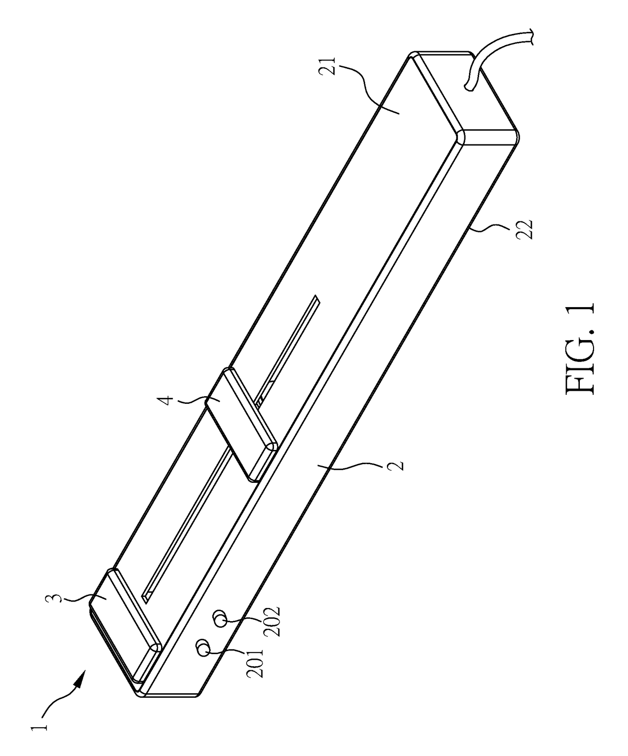
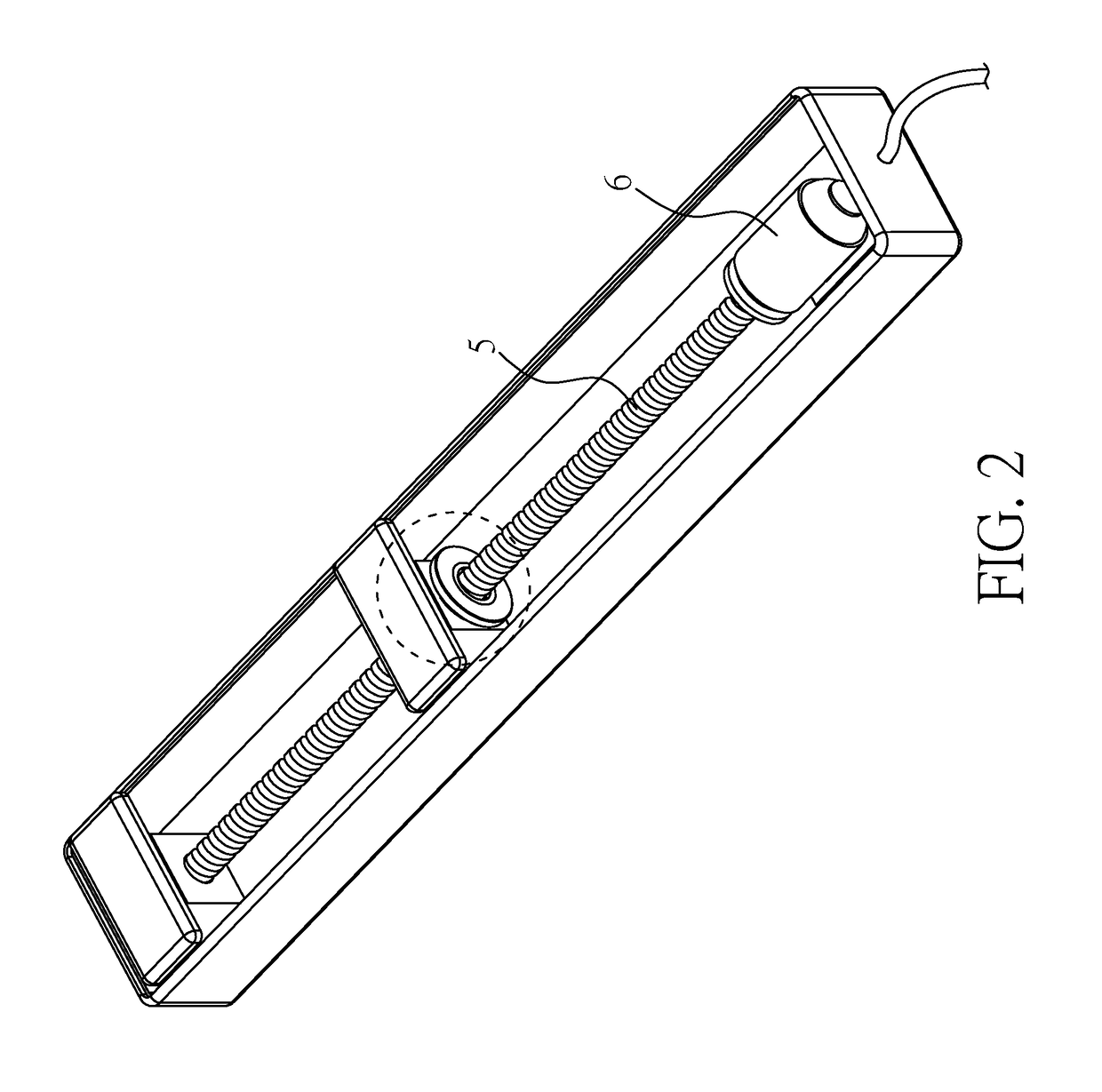
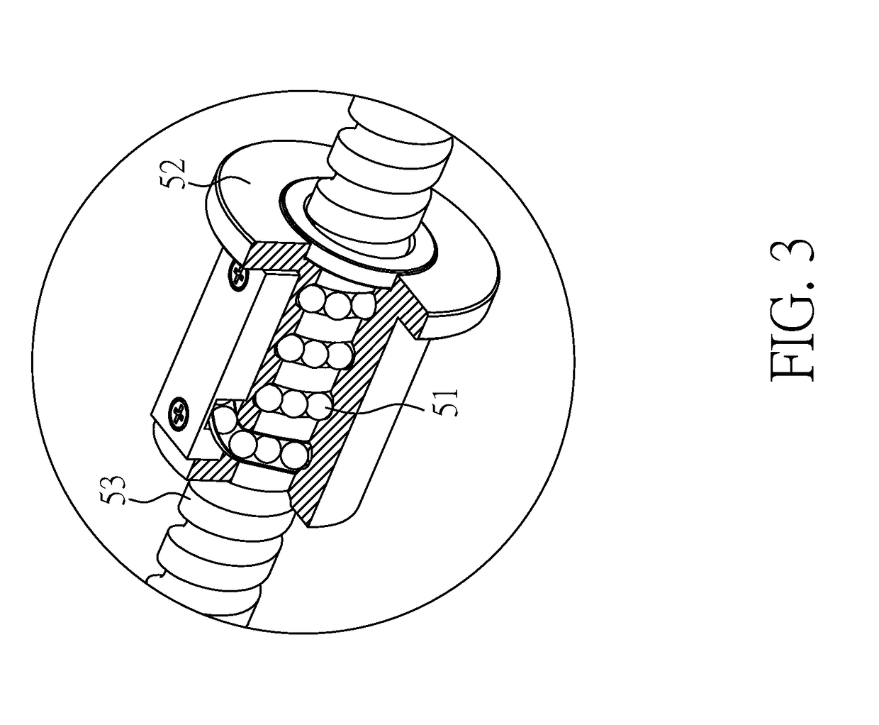
[0034]FIG. 1. is a schematic diagram of an ablation device of a first preferred embodiment. FIG. 2 is a partial schematic diagram of the embodiment of FIG. 1; FIG. 3 is a schematic diagram showing a partial enlargement of the moving unit of FIG. 2. This embodiment includes: an ablation device 1 comprising: a substrate 2 having a first surface 21; a first electrode 3 disposed on the first surface 21; a second electrode 4 disposed on the first surface 21 and adjacent to the first electrode 3; a moving unit 5 electrically connected to the second electrode 4 for moving the second electrode 4 to regulate the distance between the second electrode 4 and the first electrode 3; and a radio frequency generator (not shown) connected to the ablation device 1 for providing a radio frequency current to the first electrode 3 and the second electrode 4. The moving unit 5 is a ball screw, as shown in the partial enlargement diagram of FIG. 3. The ball screw 5 improves poor positioning and prevents d...

embodiment 2

[0036]FIG. 4 is a schematic diagram of an ablation device of another embodiment of the present invention. The ablation device of the non-invasive radio-frequency ablation system in the present embodiment is similar to that of Embodiment 1 except for the following differences.

[0037]Referring to FIG. 4, the ablation device in the present embodiment may optionally comprise a cooling unit 7, a temperature sensing unit 8, and a treatment depth sensing unit 9. The cooling unit 7 may be disposed on the first surface 21 of the substrate 2 and between the first electrode 3 and the second electrode 4. In the present embodiment, the ablation device is illustrated as including each of the cooling unit 7, the temperature sensing unit 8 and treatment the depth sensing unit 9. However, any one or more of the cooling unit 7, the temperature sensing unit 8 and treatment depth sensing unit 9 may also be omitted.

[0038]The cooling unit 7 may include a cooling chip and / or a refrigerant to lower the temp...

embodiment 3

[0041]FIG. 5 is a schematic diagram of an ablation device according to another embodiment of the present invention. The ablation device of the non-invasive radio-frequency ablation system in the present embodiment is similar to that of Embodiment 1 or 2 except for the following differences.

[0042]Referring to FIG. 5, the ablation device of the present embodiment may optionally comprise a cooling unit 7, a temperature sensing unit 8, and a treatment depth sensing unit 9. The cooling unit 7 may be disposed on the first surface 21 of the substrate 2 and between the first electrode 3 and the second electrode 4.

[0043]The temperature sensing unit 8 may be disposed on the second surface 22 of the substrate 2 and opposite to the first electrode 3, but the location of the temperature sensing unit may be varied without departing from the invention.

[0044]The treatment depth sensing unit 9 may be disposed on the second surface 22 of the substrate 2 and opposite to the cooling unit 7, but the loc...


PUM


Abstract

An ablation device of a non-invasive radio-frequency ablation system includes a substrate having a first surface; a first electrode disposed on the first surface; a second electrode disposed on the first surface and adjacent to the first electrode; a moving unit electrically connected to the second electrode for moving the second electrode to regulate the distance between the second electrode and the first electrode; and a radio frequency generator connected to the ablation device for providing a radio frequency current to the first electrode and the second electrode. According to a method using the ablation device, the first and second electrodes are brought into contact with a third surface belonging to a subject in need of treatment, and the radio frequency current is applied to the electrodes to carry out a treatment procedure. The treatment depth and area are adjusted by changing the relative distance between the electrodes.

Description

BACKGROUND OF THE INVENTION1. Field of the Invention[0001]The present disclosure relates to a non-invasive radio-frequency ablation (RFA) system and a method for treating mucosal or soft tissue related diseases and, more particularly, to a method for treating tubular soft tissue related diseases.2. Description of Related Art[0002]Radio-frequency ablation (RFA) is one of the most commonly used methods in surgical treatment. It can be applied in a variety of fields such as treatment of liver cancer, lung cancer and other tumors, thyroid nodules, and heart disease, in plastic surgery, and in otolaryngology for treatment of chronic hypertrophic rhinitis, chronic hypertrophic pharyngitis, and patients with sleep snoring . . . etc.[0003]In RFA, an electrode on a metal probe (so call mono-polar RFA) or two probes with electrodes situated at a fixed-distance (so call bi-polar RFA) are inserted into a tissue, and used to heat up the tissue between the two electrodes by introducing a current ...

Claims


Application Information

Patent Timeline
Patent Type & Authority Applications(United States)
IPC IPC(8): A61B18/14A61B8/12
CPCA61B18/14A61B2018/00738A61B2018/00577A61B8/12A61B18/1402A61B18/1485A61B18/1492A61B2018/00011A61B2018/00047A61B2018/00196A61B2018/00327A61B2018/00488A61B2018/005A61B2018/00517A61B2018/00642A61B2018/00714A61B2018/00815A61B2018/1497A61B2018/162
Inventor SU, SEA-QUAN
Owner SU SEA QUAN
Learn More