Shaping material supply device and three-dimensional shaping apparatus

a technology of shaping material and supply device, which is applied in the direction of additive manufacturing process, applying layer means, manufacturing tools, etc., can solve the problems of inability to manufacture three-dimensional shaped objects, material delay, and inability to control the flow rate of shaping material discharged from the nozzle, so as to increase the shaping accuracy of three-dimensional shaped objects, simple configuration, and cut the effect of shaping materials

Active Publication Date: 2019-02-28
SEIKO EPSON CORP
View PDF0 Cites 25 Cited by
  • Summary
  • Abstract
  • Description
  • Claims
  • Application Information

AI Technical Summary

Benefits of technology

[0065]In this configuration, since a shape of an end of the shaping material can be adapted to a certain shape, it is possible to increase shaping accuracy of a three-dimensional shaped object.
[0066]In the t...

Problems solved by technology

However, a flow rate of a shaping material discharged from the nozzle is not controlled.
Therefore, in a case where a three-dimensional shaped object has a complicated structure, it is not possible to manufacture a three-dimensional shaped object by properly changing the flow rate depending on a site to be formed.
Further, in a case of stopping discharge of the material from the nozzle, outflow of the material from the nozzle is not immediately stopped, and thus, there is a case where timing of stopping the discharge of the material is delayed or a case where a discharge amount of the material becomes excessive than an amount as planned.
However, since the material feed device and the fiber introduction device are relatively distant from the head, it is difficult to stop injection of the material with good response.
Further, in the shaping process with a three-dimensional shaping apparatus, in a case where delivery of the resin material from the nozzle is stopped, there is a problem (hereinafter also referred to as “stringing”) that, between a ...

Method used


Image

  • Shaping material supply device and three-dimensional shaping apparatus
  • Shaping material supply device and three-dimensional shaping apparatus
  • Shaping material supply device and three-dimensional shaping apparatus

Examples


first embodiment

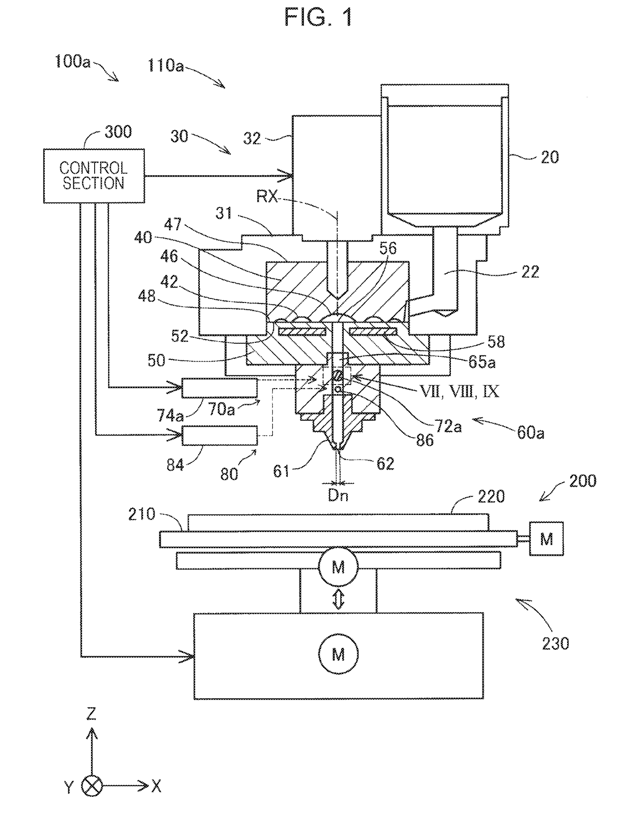
[0136]FIG. 1 is a schematic view showing a configuration of a three-dimensional shaping apparatus 100a according to a first embodiment.

[0137]The three-dimensional shaping apparatus 100a includes a discharge unit 110a, a shaping stage section 200, and a control section 300. In the three-dimensional shaping apparatus 100a, under control of the control section 300, a three-dimensional shaped object is shaped by discharging a shaping material from the nozzle 61 of the discharge unit 110a onto the shaping pedestal 220 of the shaping stage section 200.

[0138]The discharge unit 110a includes a material supply portion 20, a shaping material production section 30, and a shaping material supply device 60a. The material supply portion 20 is constituted by a hopper, and a lower outlet port is connected to the shaping material production section 30 via a communication path 22. The material supply portion supplies a material having thermoplastic properties to the shaping material production sectio...

second embodiment

[0197]FIG. 11 is a schematic diagram showing a configuration of a flow rate regulation mechanism 70b included in a shaping material supply device 60b of a three-dimensional shaping apparatus 100b according to a second embodiment. Specifically, FIG. 11 is a cross-sectional view taken along a plane perpendicular to the center axis AX of a drive shaft 76b, including the center axis of the flow direction Fd of the shaping material in a first flow path 65b. A configuration of the three-dimensional shaping apparatus 100b of the second embodiment is almost the same as that of the three-dimensional shaping apparatus 100a of the first embodiment except that the flow rate regulation mechanism 70b of the second embodiment is provided instead of the flow rate regulation mechanism 70a of the first embodiment.

[0198]The flow rate regulation mechanism 70b of the second embodiment includes a butterfly valve 72b, a valve drive portion 74b (not shown), and a drive shaft 76b. A length of one side of th...

third embodiment

[0203]With reference to FIGS. 13 and 14, a configuration of a suction section 75 included as a shaping material supply device 60c in a three-dimensional shaping apparatus 100c of a third embodiment will be described. A configuration of the three-dimensional shaping apparatus 100c of the third embodiment is almost the same as that of the three-dimensional shaping apparatus 100a of the first embodiment except that the shaping material supply device 60c of the third embodiment is provided instead of the shaping material supply device 60a of the first embodiment.

[0204]FIG. 13 is a schematic cross-sectional view showing the shaping material supply device 60c according to the third embodiment which includes the suction section 75. The suction section 75 has a function of changing a pressure in the first flow path 65a. The suction section 75 includes a branched flow path 79, a rod 77, and a rod drive portion 78. The branched flow path 79 is a flow path into which a part of the shaping mate...


PUM

PropertyMeasurementUnit
Pressureaaaaaaaaaa
Flow rateaaaaaaaaaa

Abstract

Provided is a shaping material supply device for use in a three-dimensional shaping apparatus, which includes a first flow path through which a shaping material flows, a nozzle that communicates with the first flow path and discharges the shaping material, and a flow rate regulation mechanism that includes a butterfly valve provided in the first flow path.

Description

[0001]This application claims priority under 35 U.S.C. § 119 to Japanese Patent Application No. 2017-160830 filed on Aug. 24, 2017, No. 2017-208816 filed on Oct. 30, 2017, No. 2017-208808 filed on Oct. 30, 2017, and No. 2017-208812 filed on Oct. 30, 2017, the entire disclosures of which are expressly incorporated by reference herein.BACKGROUND1. Technical Field[0002]The present invention relates to a shaping material supply device and a three-dimensional shaping apparatus.2. Related Art[0003]A three-dimensional shaping apparatus using a fused deposition modeling (FDM) in which a melted resin material is discharged, deposited, and cured to manufacture a three-dimensional shaped object is known (for example, JP-A-2017-35811).[0004]International Publication No. 2015 / 182675 discloses a three-dimensional shaping apparatus in which a resin material (filament) and carbon fibers are injected from a head.[0005]In the fused deposition modeling in the related art, a solid filament made of a th...

Claims


Application Information

Patent Timeline
IPC IPC(8): B29C64/209B33Y30/00B22F3/00B28B1/00
CPCB29C64/209B33Y30/00B22F3/008B28B1/001B33Y40/00B29C64/321B29C64/118B29C64/205B22F10/18B22F12/57B22F12/53B29C64/106B29C64/35Y02P10/25B29B7/823B29B7/826B29B7/42B29B7/401B29B7/402B29B7/407B29B7/408
Inventor SAITO, KOICHIYUWAKI, KOHEIMIZUKAMI, SHUNSUKENAKAMURA, KAZUHIDE
Owner SEIKO EPSON CORP
Why Eureka
Try Eureka