An elastic flapping hinge for connecting a rotor blade to a rotor hub of a rotary wing aircraft

Active Publication Date: 2019-02-28
AIRBUS HELICOPTERS DEUT GMBH
View PDF6 Cites 0 Cited by
  • Summary
  • Abstract
  • Description
  • Claims
  • Application Information

AI Technical Summary

Benefits of technology

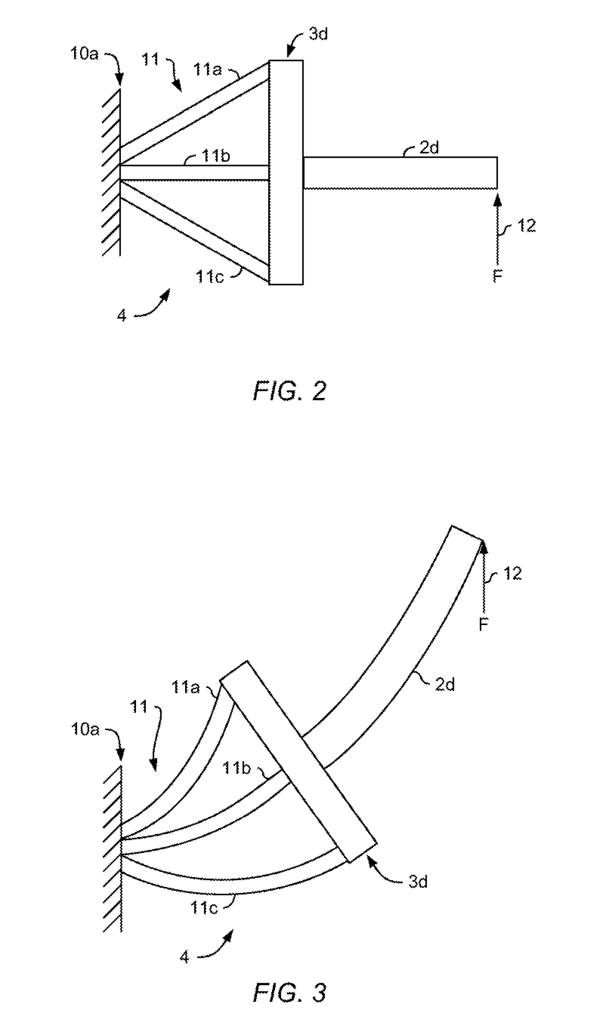
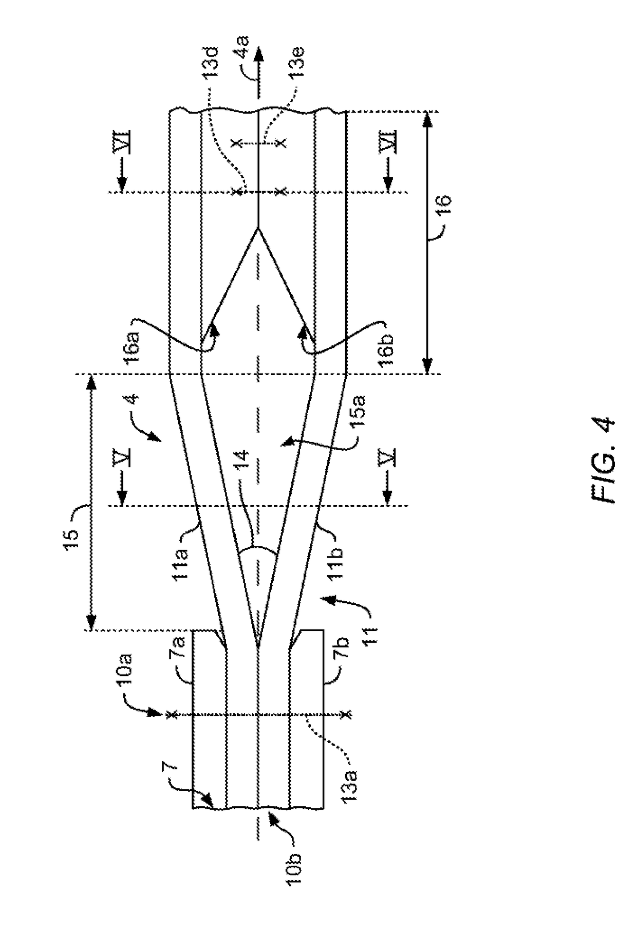
[0026]Advantageously, by not only providing the inventive elastic hinge unit with two or more elastically deformable plates, but by arranging these elastically deformable plates such that they diverge from each other in the elastic flapping hinge area by a predetermined divergence angle, the elastically deformable plates can deform in a way that, with respect to conventional configurations, significantly reduces an underlying bending stiffness contribution that emanates from the sum of respective cross-section areas of each one of the elastically deformable plates multiplied with a respective distance from its bending axis squared. Without this underlying bending stiffness contribution, each elastically deformable plate bends in operation like an individual beam element without creating the above-described S-shaped deformation. Furthermore, in this configuration associated spacer plates, blocks, webs and/or indentations advantageously prevent shear deformation and a change in distance between the individual elastically deformable plates. This leads to the full effect obtained by the sum of respective cross-section areas of each one of the elastically deformable plates multiplied with a respective distance from its bending axis squared after the elastic flapping hinge area, where a high flapping stiffness is desirable as described above.
[0027]Furthermore, by not only providing the inventive elastic hinge unit with two or more elastically deformable plates, but by arranging these elastically deformable plates such that they diverge from each other in the elastic flapping hinge area by a predetermined divergence angle, an underlying strength contribution that emanates from the sum of the respective cross-section areas of each one of the multiple parallel elastically deformable plates multiplied with a respective distance from its bending axis squared and divided by a given largest distance from the bending axis is, with respect to conventional configurations, significantly reduced. In fact, when a thick plate is split into n thinner plates with the same total thickness, then the sum of all individual strengths of the n thinner plates is only reduced by 1/n, while the sum of all individual bending stiffnesses of the n thinner plates is reduced by 1/(n2). This means that the ratio between bending strength and bending stiffness is increased by the factor n. However, when sizing each one of the n thinner plates for the sa

Problems solved by technology

A large flapping hinge distance in a bearingless or a hinge- and bearingless rotor system allows, during operation, for a good control response and maneuverability of the rotary wing aircraft, but unfortunately also leads to a high natural flapping frequency.
This relatively high natural flapping frequency and

Method used


Image

  • An elastic flapping hinge for connecting a rotor blade to a rotor hub of a rotary wing aircraft
  • An elastic flapping hinge for connecting a rotor blade to a rotor hub of a rotary wing aircraft
  • An elastic flapping hinge for connecting a rotor blade to a rotor hub of a rotary wing aircraft

Examples


Example

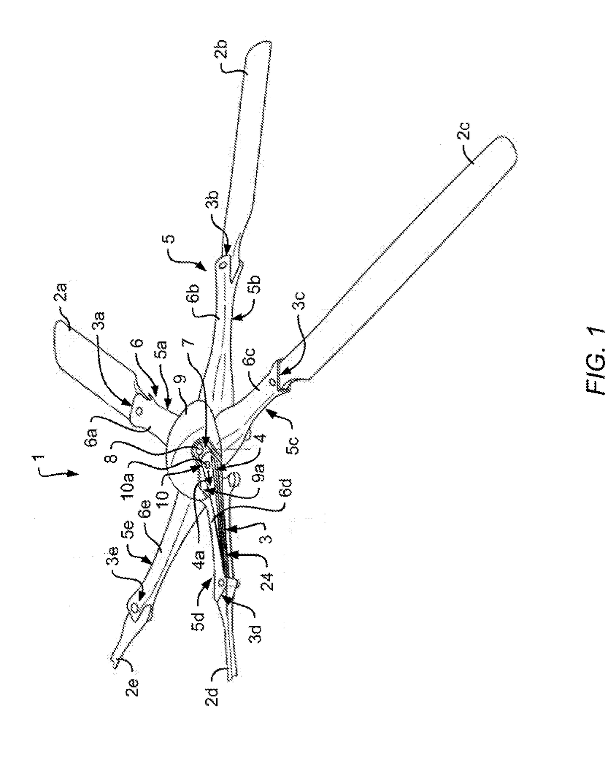
[0061]FIG. 1 shows a multi-blade rotor 1 of a rotary wing aircraft, in particular a multi-blade rotor for a main rotor of a helicopter. The multi-blade rotor 1 illustratively comprises a rotor shaft 8 that is embodied with a rotor hub 7. Furthermore, a rotor head covering cap 9 is provided for covering a central portion of the multi-blade rotor 1, which comprises the rotor hub 7 and which illustratively defines an associated rotor head. The rotor head covering cap 9 is shown with an illustrative cut-out 9a, where the rotor head covering cap 9 is partially cut away in order to permit amongst others the illustration of the rotor hub 7.

[0062]The multi-blade rotor 1 is preferably embodied as a bearingless rotor having a multiplicity of elastic hinge units 3 as interfaces between the rotor shaft 8, i. e. the rotor hub 7, and a plurality of rotor blades 2a, 2b, 2c, 2d, 2e. It should, however, be noted that these rotor blades 2a, 2b, 2c, 2d, 2e are not shown in greater detail, neither in F...


PUM


Abstract

An elastic flapping hinge for connecting a rotor blade to a rotor hub of a rotary wing aircraft, comprising an elastic flapping hinge member arrangement that includes a hub attachment area for attachment to the rotor hub, a connection area for attachment to the rotor blade, and an elastic flapping hinge area that is arranged between the hub attachment area and the connection area and adapted to allow flapping movements, the elastic flapping hinge member arrangement comprising at least two elastic flapping hinge members having a first bending stiffness for flapping movements and a second bending stiffness for lead-lag movements, the first bending stiffness being smaller than the second bending stiffness, wherein the at least two elastic flapping hinge members diverge from each other in the elastic flapping hinge area by a predetermined divergence angle.

Description

CROSS-REFERENCE TO RELATED APPLICATIONS[0001]This application claims priority to European patent application No. EP 17400052.1 filed on Aug. 28, 2017, the disclosure of which is incorporated in its entirety by reference herein.BACKGROUND OF THE INVENTION(1) Field of the Invention[0002]The invention is related to an elastic flapping hinge for connecting a rotor blade to a rotor hub of a rotary wing aircraft.(2) Description of Related Art[0003]In bearingless or hinge- and bearingless rotor systems, elastic hinge units are used to connect rotor blades of a multi-blade rotor of a rotary wing aircraft to an associated rotor hub or shaft of the aircraft. During operation, i. e. rotation of the multi-blade rotor, a respective elastic hinge unit must withstand tremendous centrifugal forces that the rotor blades apply thereto, while permitting their flapping, pitch and lead-lag motions.[0004]Such an elastic hinge unit is usually implemented by means of a so-called “flexbeam unit”. In general...

Claims


Application Information

Patent Timeline
IPC IPC(8): B64C27/33B64C27/48B64C27/635
CPCB64C27/33B64C27/48B64C27/635
Inventor BUESING, MORITZPFALLER, RUPERTORTNER, MARTIN
Owner AIRBUS HELICOPTERS DEUT GMBH
Why Eureka
Try Eureka