Optical lens head, camera module and assembling method therefor

a technology of optical lens and camera module, which is applied in the field of optical lens assembly and camera module, and the assembly method thereof, can solve the problems of affecting the optical performance affecting the imaging quality, and the disassembly of the lens module, and achieves high imaging quality of the lens and the camera module. , the effect of high assembly precision

Active Publication Date: 2019-02-28
NINGBO SUNNY OPOTECH CO LTD
View PDF6 Cites 10 Cited by
  • Summary
  • Abstract
  • Description
  • Claims
  • Application Information

AI Technical Summary

Benefits of technology

[0005]An objective of the present disclosure includes providing an optical lens assembly, a camera module, and assembly methods thereof, where the lenses are assembled without connecting a structural member, and are assembled by lens embedding, so that the assembly precision is high, the tolerance is low, and the imaging quality of the lenses and the camera module is high.
[0006]An objective of the present disclosure includes providing an optical lens assembly, a camera module, and assembly methods thereof. According to an optical path design, a partial portion of an optical lens is opaqued to arrange a connecting portion to directly embedding optical lenses, so that the spacer ring in the conventional camera module is omitted, the tolerance brought by assembly of the spacer ring is avoided, the assembly precision is improved, the manufacturing of the lens assembly and the camera module is simpler, and the production efficiency is higher.
[0007]An objective of the present disclosure includes providing an optical lens assembly, a camera module and assembly methods thereof. The lens assembly or the camera module uses lenses on which a blackening process and a matting process are performed and does not use structural members for connection, so that the cost is reduced.

Problems solved by technology

The precision of assembling the spacer ring and manufacturing the diaphragm is much lower than that of machining and manufacturing the lenses, there is a risk of assembly deviation for connecting the lenses by the spacer ring and the stopper, and the machining precision is poor or the thickness is large, such that stray lights of an optical system are likely caused to affect the imaging quality; or the lenses are eccentric or skewed due to the tolerance of the components of the lens assembly or a poor assembly technology, thus affecting the optical performance of the lens module.
Moreover, the above manufacture steps are complicated, and have many working procedures and a high cost, the quality of the manufactured product is difficult to be controlled and productivity and yield can not be improved.
In addition, when the conventional lens assembly is assembled, a plurality of lenses need to be connected with spacer rings, and the spacer rings need to occupy spaces, thus increasing the lens size and thus increasing the module size, which not only consumes raw materials, but also is not conducive to developing a thin and light product; moreover, the fixation of the lenses must use glue, and the components of the lens assembly can only be fixed by adhesive dispensing one by one, thus reducing the production efficiency and further leading to high production cost.

Method used


Image

  • Optical lens head, camera module and assembling method therefor
  • Optical lens head, camera module and assembling method therefor
  • Optical lens head, camera module and assembling method therefor

Examples


Embodiment Construction

[0114]The following description is provided to disclose the present disclosure to enable those skilled in the art to implement the present disclosure. Preferred embodiments are provided in the following description only as examples and modifications will be apparent to those skilled in the art. The general principles of the present disclosure defined in the following description may be applied to other embodiments, alternatives, modifications, equivalents, and other technical solutions without departing from the spirit and scope of the present disclosure.

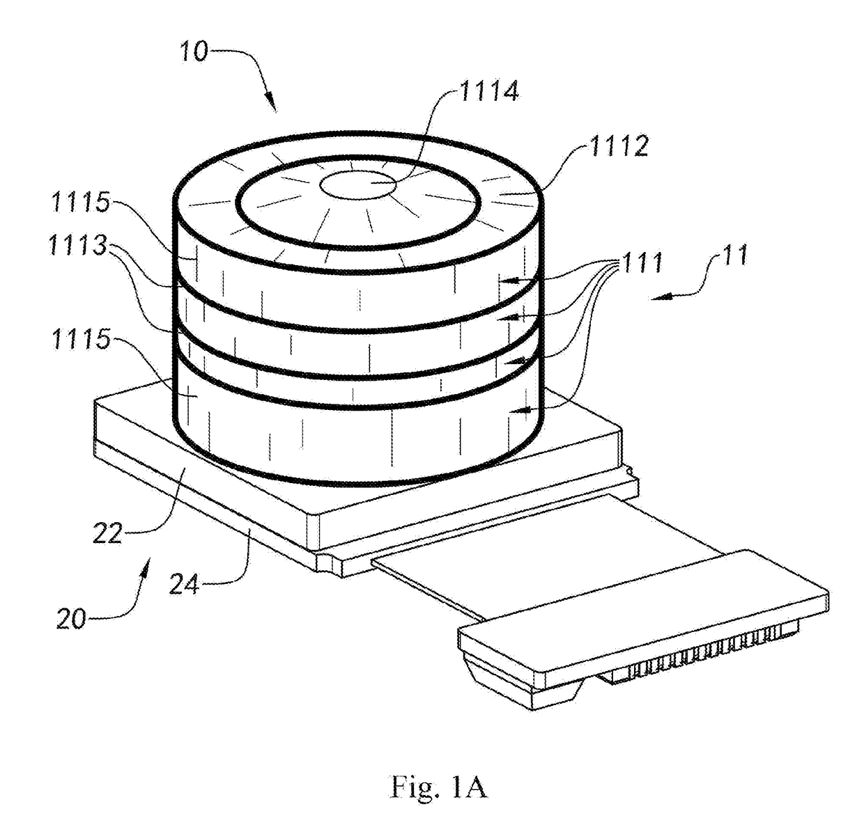
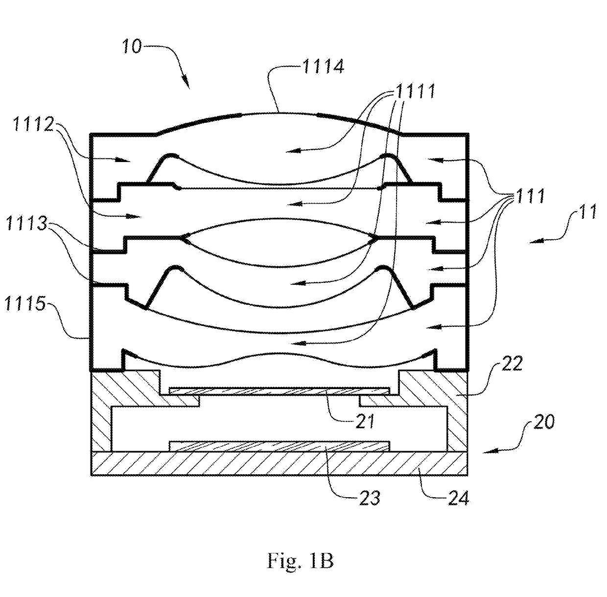
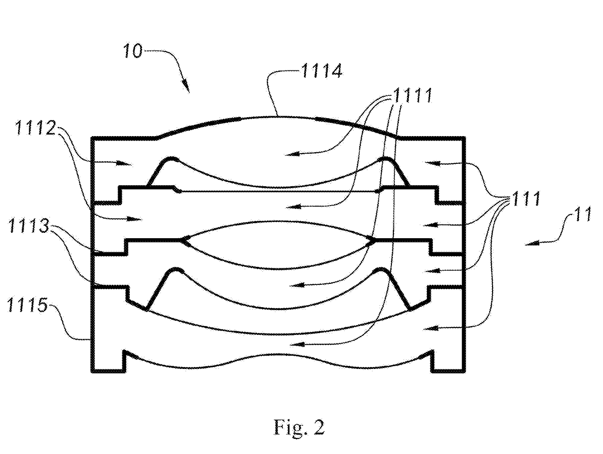
[0115]Referring to FIG. 1A to FIG. 4, a first specific implementation of an optical system structure according to the present disclosure will be explained. As shown in FIG. 1A to FIG. 4, an camera module includes an optical lens assembly 10 and a photosensitive device 20; the photosensitive device 20 is manufactured by a COB (chip on board) process and includes a color filter 21, a lens holder 22, a photosensitive chip 23 and a circ...


PUM


Abstract

An optical lens head, an camera module, and an assembling method therefor, wherein the camera module comprises a photosensitive chip (23) and an optical lens head (10); said optical lens head (10) comprises a plurality of optical lenses (111); the assembly position of one of the optical lenses (111) is adjustable; each of the optical lenses (111) is black-lacquered and matte-treated; a connecting portion (1113), a light-beam entrance hole (1114) and a light-shielding portion (1115) are formed on the corresponding optical lenses (111), such that the individual optical lenses (111) can be successively and jointly assembled together, eliminating the need of a spacing ring, a diaphragm, a lens barrel and other structural components used in a conventional camera module, thereby improving manufacture precision, production yield and imaging quality of the camera module.

Description

TECHNICAL FIELD[0001]The present disclosure relates to the field of camera modules, and particularly relates to an optical lens assembly, a camera module, and assembly methods thereof.BACKGROUND[0002]In a conventional assembly process of a camera module, a lens assembly is an independently assembled component, and includes a lens barrel (including a diaphragm), a lens, a spacer ring, a stopper and other structures. The assembly process of the lens assembly includes: mounting the spacer ring and lens into the lens barrel in sequence, pressing the spacer ring on the lens, fixing the spacer ring with the side wall of the lens barrel through adhesive dispensing, and fixing the last lens with glue or a stopper to realize the assembly of the lens assembly. The precision of assembling the spacer ring and manufacturing the diaphragm is much lower than that of machining and manufacturing the lenses, there is a risk of assembly deviation for connecting the lenses by the spacer ring and the st...

Claims


Application Information

Patent Timeline
Patent Type & Authority Applications(United States)
IPC IPC(8): G02B5/00G02B7/02G03B17/12
CPCG02B5/005G02B7/021G03B17/12H04N5/2254G02B7/025H04N23/55H04N23/57
Inventor WANG, MINGZHUGUO, NANJIANG, HENGLIU, CHUNMEI
Owner NINGBO SUNNY OPOTECH CO LTD
Why Eureka
Try Eureka