Light source device and projection display apparatus

Active Publication Date: 2019-02-28
PANASONIC INTELLECTUAL PROPERTY MANAGEMENT CO LTD
View PDF1 Cites 4 Cited by
  • Summary
  • Abstract
  • Description
  • Claims
  • Application Information

AI Technical Summary

Benefits of technology

[0006]In accordance with the present disclosure, it is possible to configure the light source device that features a small size, a wide color gamut, and high luminance while eliminating speckle noises and fine unevenness in luminance, through the use of: the solid-state light sources for emitting the blue, the green, and the red light; the small-size dichroic

Problems solved by technology

When an image is formed on a screen, use of laser li

Method used


Image

  • Light source device and projection display apparatus
  • Light source device and projection display apparatus
  • Light source device and projection display apparatus

Examples


Example

First Exemplary Embodiment

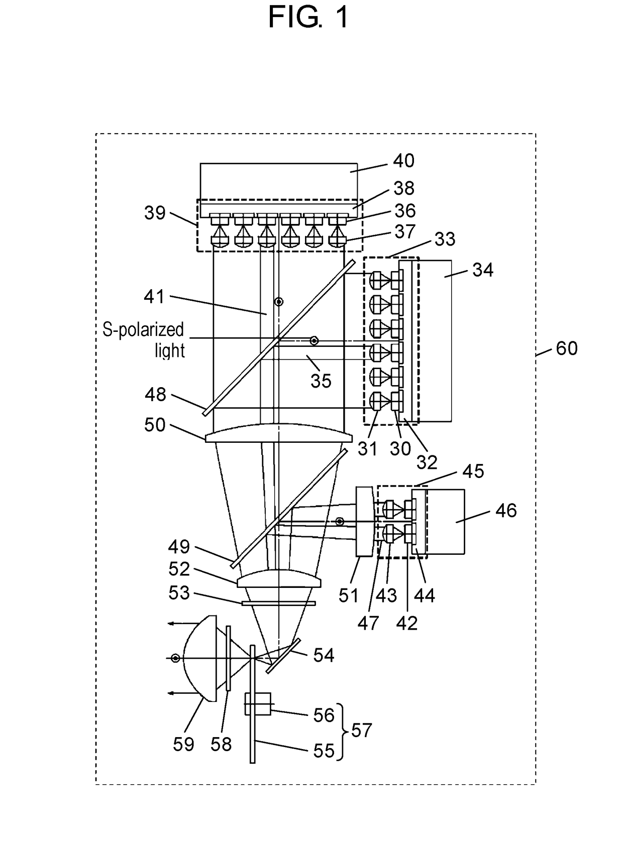
[0013]FIG. 1 is a view of a configuration of light source device 60 according to a first embodiment.

[0014]Red laser light source 33 is configured with: red semiconductor lasers 30 being red solid-state light sources; collimator lenses 31; and heat dissipation plate 32. Green laser light source 39 is configured with: green semiconductor lasers 36 being green solid-state light sources; collimator lenses 37; and heat dissipation plate 38. Blue laser light source 45 is configured with: blue semiconductor lasers 42 being blue solid-state light sources; collimator lenses 43 and heat dissipation plate 44.

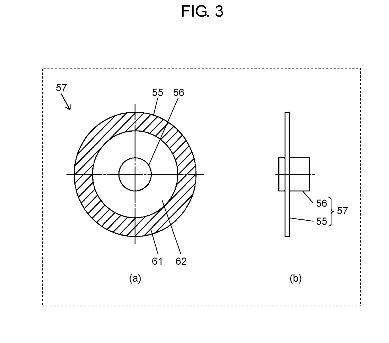
[0015]Moreover, light source device 60 includes: heat sinks 34, 40, and 46; red-reflection dichroic mirror 48; blue-reflection dichroic mirror 49; condenser lenses 50, 51, 52, and 59; diffusion plates 53 and 58; rotary diffusion plate 57 which is a dynamic diffusion plate and is configured with circular diffusion plate 55 and motor 56; and reflection mirror 54. FI...

Example

[0041]FIG. 4 is a view of a first projection display apparatus according to a second embodiment of the present disclosure.

[0042]First projection display apparatus 200 includes image forming elements each of which employs an active-matrix, transmissive liquid crystal panel, either a twisted nematic (TN) mode or a vertical alignment (VA) mode. The pixel region of the panel is provided with thin-film transistors.

[0043]Light source device 60 of first projection display apparatus 200 is configured including: red laser light source 33, green laser light source 39, blue laser light source 45, heat sinks 34, 40, and 46, red-reflection dichroic mirror 48, blue-reflection dichroic mirror 49, condenser lenses 50, 51, and 52, diffusion plate 53, reflection mirror 54, rotary diffusion plate 57 configured with circular diffusion plate 55 and motor 56, diffusion plate 58, and condenser lens 59. The light source device described above is the same as that described in the first embodiment of the pre...

Example

[0053]FIG. 5 is a view of a second projection display apparatus according to a third embodiment of the present disclosure. The second projection display apparatus uses image forming elements that are three mirror-deflection DMDs.

[0054]Light source device 63 of second projection display apparatus 300 is configured with: red laser light source 33, green laser light source 39, blue laser light source 45, heat sinks 34, 40, and 46, red-reflection dichroic mirror 48, blue-reflection dichroic mirror 49, condenser lenses 50, 51, and 52, diffusion plate 53, reflection mirror 54, rotary diffusion plate 57 configured with circular diffusion plate 55 and motor 56, and diffusion plate 58. This light source device is different from the light source device according to the first embodiment of the present disclosure in that condenser lens 59 is not disposed.

[0055]White light having exited from light source device 63 is converged onto rod 301. The light incident on rod 301 is subjected to multiple-...


PUM


Abstract

The light source device of the projection display apparatus according to the present disclosure includes: solid-state light sources that individually emit blue light, green light, and red light; a plurality of dichroic mirrors that combine the blue light, the green light, and the red light having exited from the solid-state light sources; a first diffusion plate on which the combined light having been combined by the plurality of dichroic mirrors is incident; a dynamic diffusion plate that is disposed at a position at which the combined light having exited from the first diffusion plate converges and starts to diverge.

Description

BACKGROUND1. Technical Field[0001]The present disclosure relates to projection display apparatuses each of which enlarges and projects images onto a screen by using a projection lens, with such images being formed by image forming elements that are irradiated with illumination light.2. Description of the Related Art[0002]Many types of light source devices have been disclosed which are to be used as light sources for projection display apparatuses that employ mirror-deflection digital micromirror devices (DMDs) or light valves using liquid crystal panels. Such light source devices use solid-state light sources featuring long service life, such as semiconductor lasers and light-emitting diodes. Among them, a light source device featuring a wide color gamut and high efficiency has been disclosed which uses a blue, a green, and a red solid-state light source.[0003]When an image is formed on a screen, use of laser light being highly coherent will cause speckle noises. A technology for el...

Claims


Application Information

Patent Timeline
IPC IPC(8): G02B5/02H04N9/31G03B27/48G02B27/48
CPCG02B5/0236H04N9/3161G03B27/48G02B5/0278G02B27/48G03B21/2013G03B21/206G03B21/208H04N9/3164G03B21/2033G03B21/2073G03B33/06G02B27/0933G02B27/102
Inventor TANAKA, TAKAAKI
Owner PANASONIC INTELLECTUAL PROPERTY MANAGEMENT CO LTD
Why Eureka
Try Eureka