Eureka AIR delivers breakthrough ideas for toughest innovation challenges, trusted by R&D personnel around the world.

Transflective liquid crystal display

Inactive Publication Date: 2019-02-28
SHENZHEN CHINA STAR OPTOELECTRONICS SEMICON DISPLAY TECH CO LTD
View PDF2 Cites 2 Cited by
  • Summary
  • Abstract
  • Description
  • Claims
  • Application Information

AI Technical Summary

Benefits of technology

The present invention provides a transflective liquid crystal display that increases brightness when external lighting is high and has a high transmission rate. It requires no additional insulation layer and has a simple structure. The display has a reflective electrode on a black matrix and a pixel electrode, which makes a reflective zone and a transmissive zone, respectively. The reflective zone does not occupy the transmissive zone, and the transmission rate of the device is not affected. The liquid crystal cell thicknesses in the reflective and transmissive zones can be controlled through controlling the thickness of the black matrix, without adding extra insulation layer.

Problems solved by technology

However, for outdoor use, since the external lighting is excessively strong, the magnitude of the backlighting is affected by the external light so that eyes, when viewing the display, cannot perceives clear images due to excessive brightness of the panel and this affects the image quality.
In addition, long term uses of the backlight source would consume a large amount of electrical power.
Display devices of small sizes are generally powered by electrical batteries and a situation of running out of power may readily occur.
However, in sites where light source is weak, a situation of insufficient light intensity may occur, and this affects the image quality.
The transflective liquid crystal display device, although capable of transmissive-reflective displaying, suffers the existence of the reflective zone 201′ that severely affects the transmission rate of the liquid crystal display device, and requires control of the thickness of the insulation layer 220′ such that the thickness of the liquid crystal layer 300′ in the reflective zone 201′ is one half of the thickness thereof in the transmissive zone 202′, the manufacturing process being complicated and hard to achieve.

Method used


Image

  • Transflective liquid crystal display
  • Transflective liquid crystal display
  • Transflective liquid crystal display

Examples


Embodiment Construction

[0038]To further expound the technical solution adopted in the present invention and the advantages thereof, a detailed description will be given with reference to the preferred embodiments of the present invention and the drawings thereof.

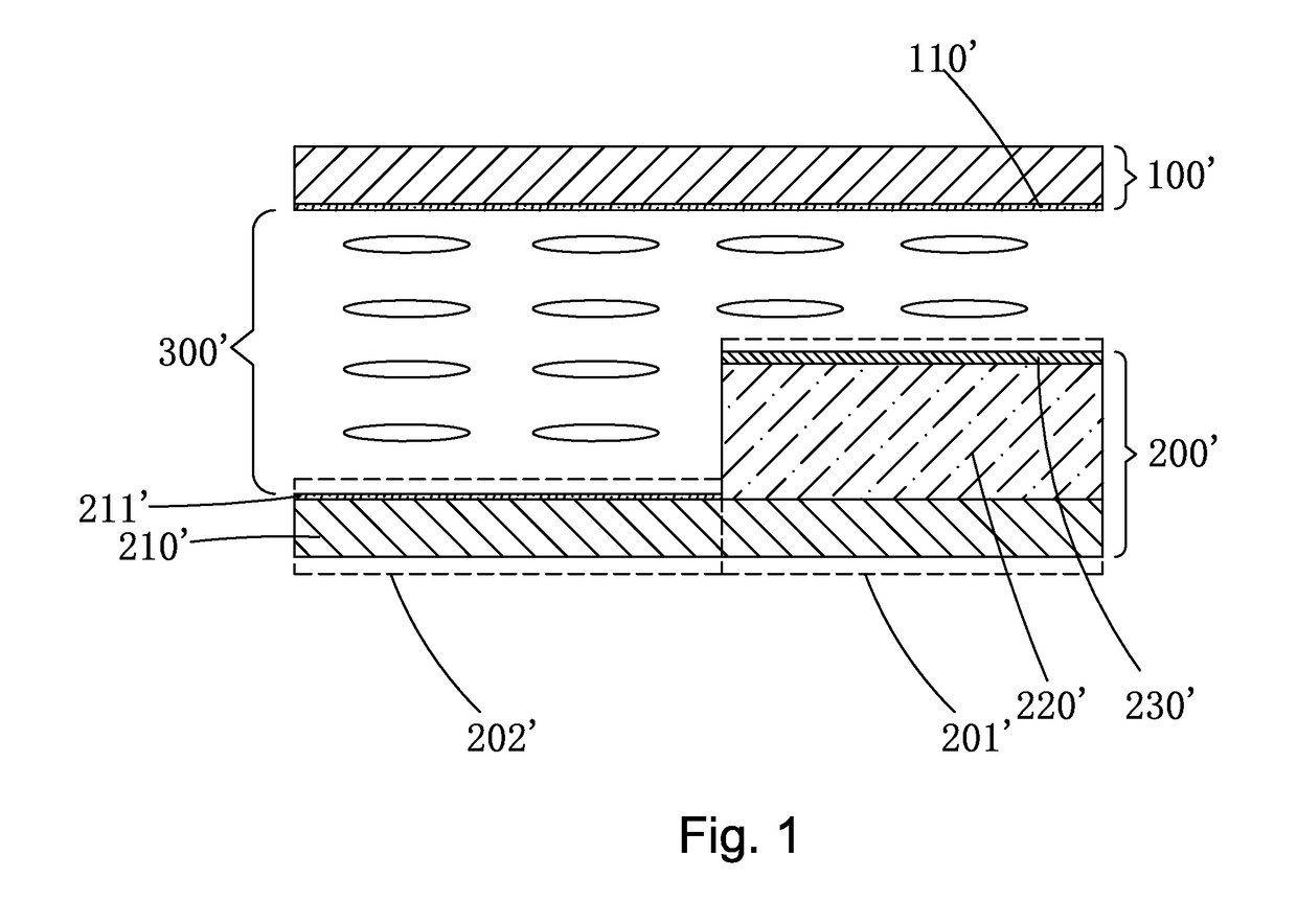
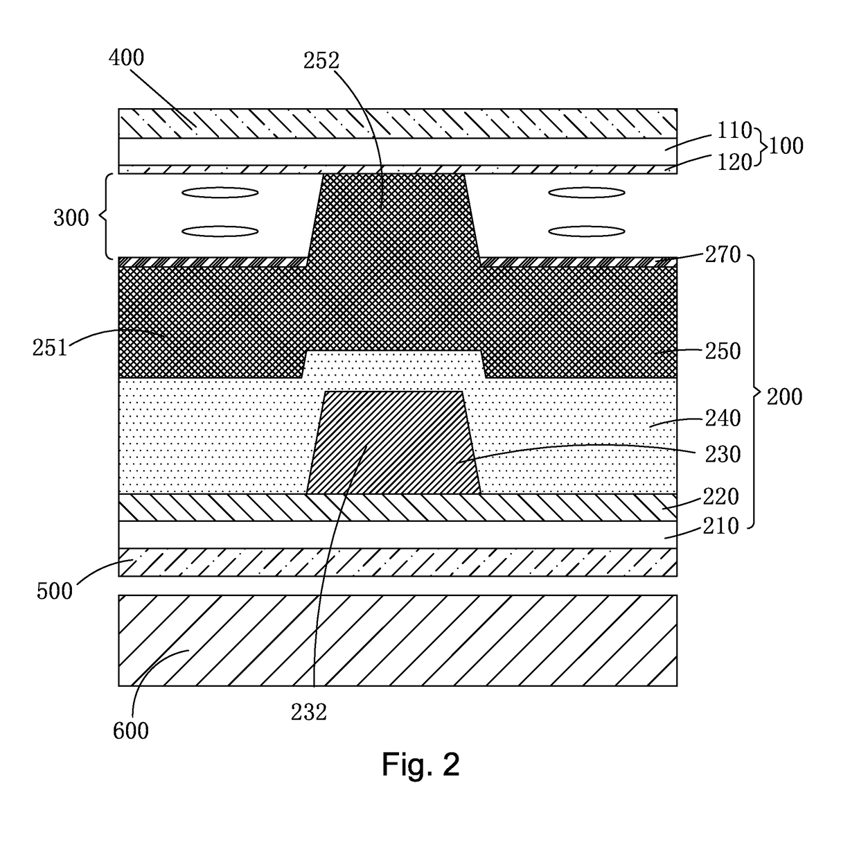
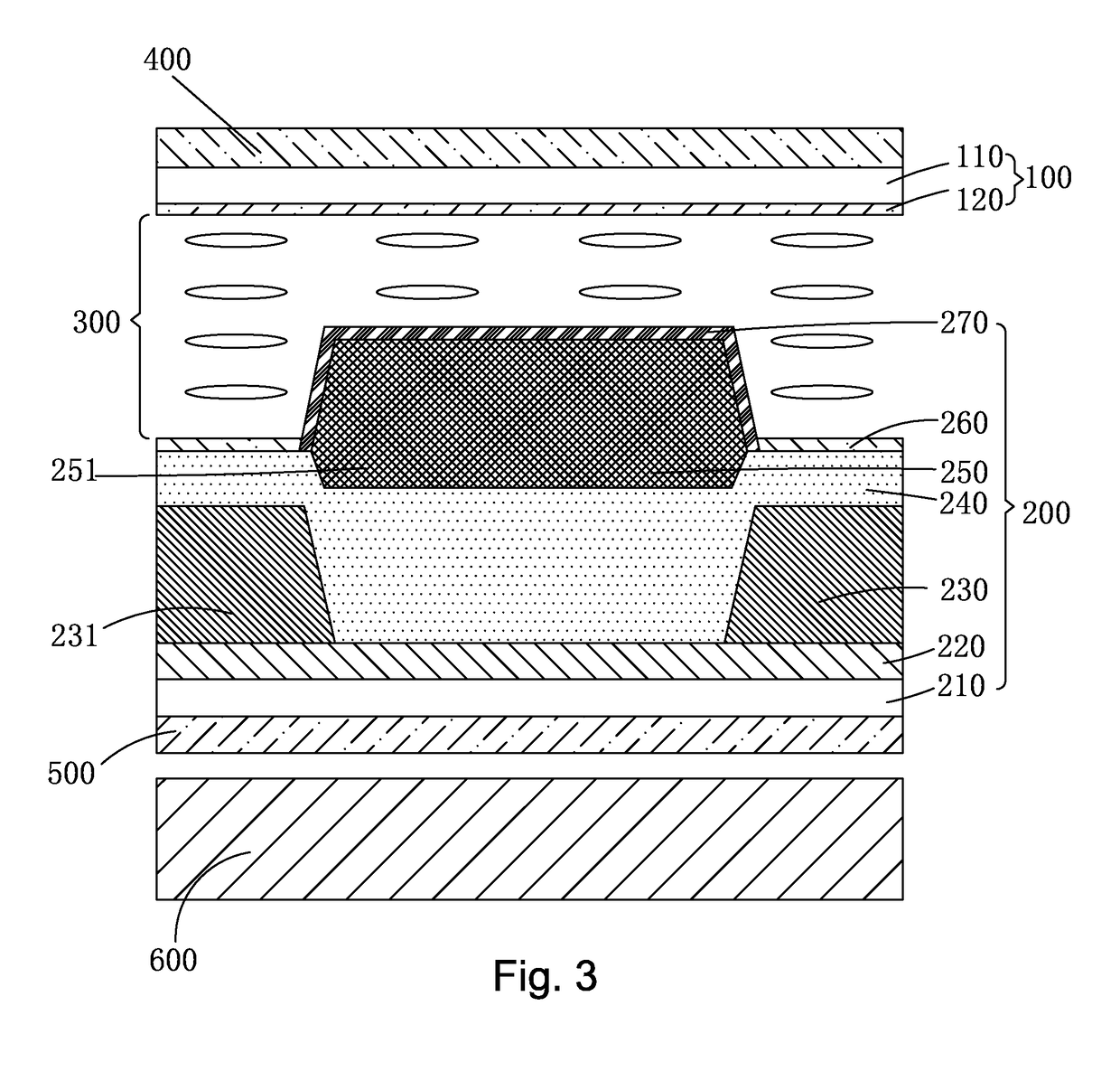
[0039]The present invention provides a transflective liquid crystal display, which involves the application of a technique that allows a color filter layer to be directly formed on an array substrate (namely Color Filter on Array, COA) and a technique that allows a black matrix and main and sub photo spacers to be formed of a black-photo-spacer (BPS) material with the same manufacturing process. Referring to FIGS. 2-5, the transflective liquid crystal display according to the present invention comprises: an upper substrate 100 and a lower substrate 200 that are arranged opposite to each other, a liquid crystal layer 300 arranged between the upper substrate 100 and the lower substrate 200, an upper polarizer plate 400 arranged on one side of the up...


PUM


Abstract

The present invention provides a transflective liquid crystal display, which adopts an arrangement involving COA and BPS and provides a reflective electrode on a black matrix of a BPS light-shielding layer and makes the reflective electrode connected to a pixel electrode so as to form a reflective zone in an area of a device that corresponds to the reflective electrode and also to form a transmissive zone in an area corresponding to the pixel electrode thereby increasing brightness of a displayed image when the external light is intense. In addition, the reflective zone does not occupy an area of the transmissive zone and thus does not affect the transmission rate of the device. Further, liquid crystal cell thicknesses in the reflective zone and the transmissive zone are controllable through controlling the thickness of the black matrix without the necessity of adding an extra insulation layer so that the structure is made simple.

Description

BACKGROUND OF THE INVENTION1. Field of the Invention[0001]The present invention relates to the field of liquid crystal display technology, and more particular to a transflective liquid crystal display.2. The Related Arts[0002]With the progress of the display technology, flat panel display devices, such as liquid crystal displays (LCDs), due to various advantages, such as high image quality, low power consumption, thin device body, and wide range of applications, have been widely used in all sorts of consumer electronic products, including mobile phones, televisions, personal digital assistants (PDAs), digital cameras, notebook computers, and desktop computers so as to take a leading position in the field of flat panel display devices.[0003]According to lighting requirement, the LCDs that are currently available in the market can be roughly divided into three categories, including transmissive liquid crystal displays, reflective liquid crystal displays, and transflective liquid cryst...

Claims


Application Information

Patent Timeline
IPC IPC(8): G02F1/1362G02F1/1368G02F1/1339G02F1/1343G02F1/1335
CPCG02F1/136209G02F1/1368G02F1/13394G02F1/13439G02F1/133553G02F1/133528G02F2001/136222G02F2201/123G02F2001/133531G02F2201/121G02F2203/09G02F1/133512G02F1/133555G02F1/133357G02F1/133371G02F1/133531G02F1/13396G02F1/13398G02F1/136222
Inventor LIU, MINGGANGLIN, YUNGLUN
Owner SHENZHEN CHINA STAR OPTOELECTRONICS SEMICON DISPLAY TECH CO LTD
Why Eureka
Eureka Blog
Learn More