Diagnostic apparatus for exhaust gas sensor

a technology of exhaust gas sensor and diagnostic apparatus, which is applied in mechanical apparatus, instruments, machines/engines, etc., can solve the problems that the deterioration in the response of the sensor may not be able to be diagnosed in an accurate manner, and achieves the effect of easy variation of oxygen concentration, high accuracy and high accuracy

Active Publication Date: 2019-03-07
TOYOTA JIDOSHA KK
View PDF0 Cites 6 Cited by
  • Summary
  • Abstract
  • Description
  • Claims
  • Application Information

AI Technical Summary

Benefits of technology

[0010]On the other hand, as mentioned above, fuel may be added to exhaust gas for the purpose of maintaining the function of an exhaust gas purification catalyst of an internal combustion engine. In addition, if a fuel addition valve is arranged in an exhaust passage, for example, fuel may be added to the exhaust passage from the fuel addition valve for preventing clogging of the fuel addition valve. Then, the function of an exhaust system of the internal combustion engine can be maintained by such an addition of fuel being carried out. Here, when fuel is added to the exhaust gas, the oxygen concentration of the exhaust gas may vary in accordance with the addition of the fuel. Accordingly, when such an addition of fuel is carried out during the execution of the above-mentioned oxygen concentration processing, the output of the exhaust gas sensor is also varied in accordance with the variation in the oxygen concentration of the exhaust gas accompanying the addition of fuel, during which it becomes difficult for the output of the exhaust gas sensor to converge. In this case, when the diagnosis of the exhaust gas sensor is tried to be made based on the converged value of the sensor output (i.e., taking the output gain of the sensor into consideration), there is a fear that the accuracy of the diagnosis may drop.
[0037]According to the present disclosure, it is possible to diagnose an exhaust gas sensor with high accuracy as much as possible while maintaining the function of an exhaust system of an internal combustion engine.

Problems solved by technology

Here, in the above-mentioned exhaust gas sensors, when an output gain of each sensor changes, abnormality in the form of deterioration in response of the sensor may not be able to be diagnosed in an accurate manner.

Method used


Image

  • Diagnostic apparatus for exhaust gas sensor
  • Diagnostic apparatus for exhaust gas sensor
  • Diagnostic apparatus for exhaust gas sensor

Examples


first embodiment

(General Configuration of Internal Combustion Engine and its Intake and Exhaust Systems)

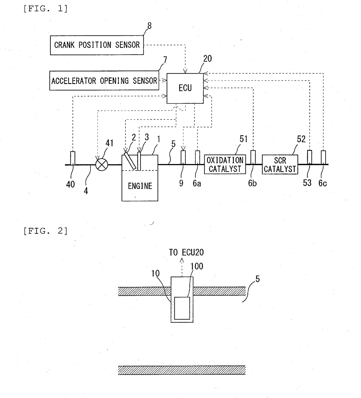
[0055]FIG. 1 is a diagram showing the general configuration of an internal combustion engine and its intake and exhaust systems according to a first embodiment of the present disclosure. The internal combustion engine, which is shown in FIG. 1 and denoted by 1, is a lean-burn internal combustion engine of spark ignition type using gasoline, etc., as fuel. However, the present disclosure can also be applied to a compression ignition type internal combustion engine (diesel engine).

[0056]The internal combustion engine 1 is provided with a fuel injection valve 2 and a spark plug 3. Here, note that the fuel injection valve 2 may be constructed so as to directly inject fuel into a cylinder, or may be constructed so as to inject fuel into an intake port of the cylinder.

[0057]The internal combustion engine 1 is connected to an intake passage 4. In the intake passage 4, there are arranged an air flow mete...

second embodiment

(General Configuration of Internal Combustion Engine and its Intake and Exhaust Systems)

[0140]Now, a second embodiment of the present disclosure will be described. FIG. 13 is a diagram showing the general configuration of an internal combustion engine and its intake and exhaust systems according to this second embodiment of the present disclosure. The internal combustion engine 1 shown in FIG. 13 is an internal combustion engine of compression ignition type (diesel engine), and is provided with a fuel injection valve 2 for injecting fuel into a cylinder. Here, note that in this second embodiment, the detailed explanation of substantially the same construction and substantially the same control processing as in the above-mentioned first embodiment will be omitted.

[0141]The internal combustion engine 1 is connected to an exhaust passage 5. In the exhaust passage 5, there are arranged a fuel addition valve 9, a first NOx sensor 60a, an NOx storage reduction catalyst 54 (hereinafter, so...

third embodiment

[0144]Now, a third embodiment of the present disclosure will be described. In the above-mentioned first embodiment, the response of an air fuel ratio sensor is diagnosed based on a response index value. In contrast to this, in this third embodiment, the response of an air fuel ratio sensor is diagnosed based on a well-known response parameter, which is a parameter with respect to the response of an air fuel ratio sensor. Here, note that in this third embodiment, the detailed explanation of substantially the same construction and substantially the same control processing as in the above-mentioned first embodiment will be omitted.

[0145]Here, according to the techniques described in the prior art literatures, etc., a response parameter is corrected based on a converged value of an air fuel ratio sensor output during the execution of fuel cut processing. However, if the above-mentioned fuel supply processing is carried out with the execution of the fuel cut processing, it becomes diffic...


PUM


Abstract

An exhaust gas sensor is diagnosed with high accuracy as much as possible while maintaining the function of an exhaust system of an internal combustion engine. In a diagnostic apparatus for an exhaust gas sensor which is applied to an internal combustion engine including an exhaust gas sensor, a fuel supplier, a controller configured to carry out predetermined fuel supply processing and predetermined oxygen concentration processing, and which diagnoses the exhaust gas sensor based on an output value thereof, provision is made for the controller that sets as a diagnostic output value a first output value, which is an output value at the side of the highest oxygen concentration in the output value of the exhaust gas sensor in a measurement period, and performs the diagnosis of the exhaust gas sensor based on the diagnostic output value, when predetermined fuel supply processing is carried out in the measurement period.

Description

CROSS-REFERENCE TO RELATED APPLICATIONS[0001]This application claims priority to Japanese Patent Application No. 2017-172109 filed on Sep. 7, 2017, the entire contents of which are incorporated by reference.BACKGROUNDTechnical Field[0002]The present disclosure relates to a diagnostic apparatus for an exhaust gas sensor.Description of the Related Art[0003]An exhaust gas sensor in the form of an air fuel ratio sensor may be arranged in an exhaust system of an internal combustion engine, in order to control an air fuel ratio of an air fuel mixture in the internal combustion engine. In addition, in an exhaust gas purification apparatus using an NOx selective catalytic reduction catalyst, an exhaust gas sensor in the form of an NOx sensor may be arranged in an exhaust system of an internal combustion engine, in order to control an amount of addition of a reducing agent. Then, with these exhaust gas sensors, output signals each corresponding to an oxygen concentration of exhaust gas are o...

Claims


Application Information

Patent Timeline
Patent Type & Authority Applications(United States)
IPC IPC(8): F01N11/00G07C5/08
CPCF01N11/007G07C5/0808F01N3/36F01N2550/00F01N2560/025F01N2610/03F01N2900/0416F01N2900/0422F01N2900/1402Y02T10/12Y02T10/40
Inventor HAGIWARA, KOJIIWAZAKI, YASUSHIKIDOKORO, TORUSAITO, HIROTAKA
Owner TOYOTA JIDOSHA KK
Why Eureka
Try Eureka