Failure diagnosis device for ignition circuit

Active Publication Date: 2019-03-14
DENSO CORP
View PDF0 Cites 0 Cited by
  • Summary
  • Abstract
  • Description
  • Claims
  • Application Information

AI Technical Summary

Benefits of technology

The present invention provides a failure diagnosis device for an ignition circuit that can determine the failure location of the ignition circuit, especially when two capacitors are connected in series. This device can simplify the ignition circuit and reduce the complexity of the failure diagnosis process. The determination unit can predict the fluctuation in the inter-terminal voltage or intermediate voltage caused by a failure and determine the fault location of the ignition circuit based on these voltage measurements. This information can be used to simplify the design and improve the reliability of the ignition circuit.

Problems solved by technology

In such case, the current value monitoring means of the switching means provided on the high side requires a complicated configuration as compared with a conventional current value monitoring means.
Since the primary current supplied from each of the capacitors to the primary coil is conducted and interrupted, an induced voltage is generated in the secondary coil, resulting in the ignition plug to generate a discharge a plurality of times. When one of the components necessary for causing the ignition plug to generate discharge fails, it becomes difficult to cause the ignition plug to generate discharge, and the determination unit determines the failure location of the ignition circuit.

Method used


Image

  • Failure diagnosis device for ignition circuit
  • Failure diagnosis device for ignition circuit
  • Failure diagnosis device for ignition circuit

Examples


example 1

Alternative Example 1

[0087]In the above embodiment, an open failure determination of the capacitor 14A is performed using the second predetermined value, or the short failure determination of the capacitor 14A is performed using the fourth predetermined value. With respect to this, instead of the above determination, as described below, it is also possible to compare a first threshold value, which is provided to determine whether or not the voltage value is substantially equal to the inter-terminal voltage Vin, with the intermediate voltage V½.

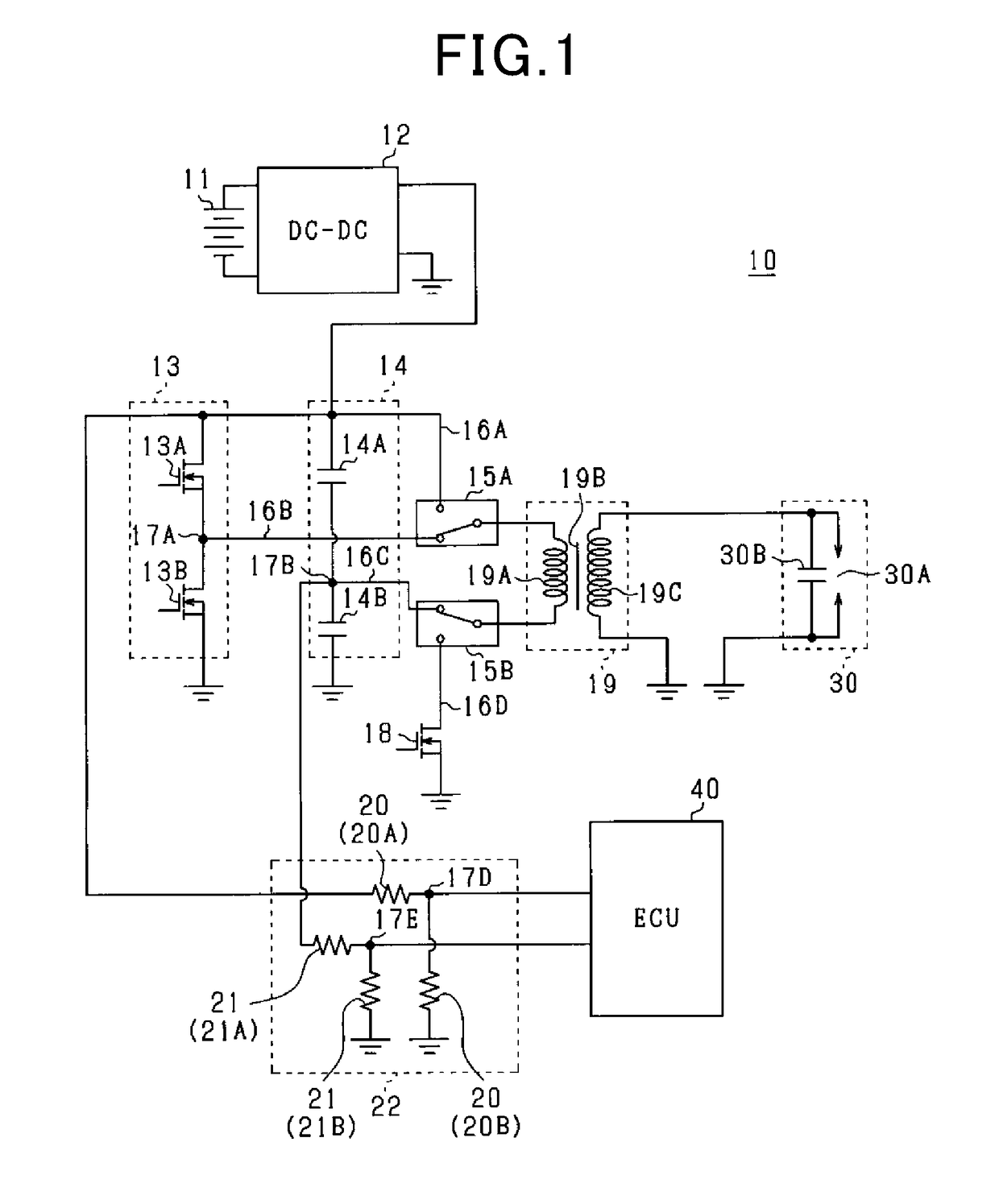
[0088]In a state where an open failure has occurred in the capacitor 14A, when the MOSFET 13A is switched from the open state to the closed state, a voltage which should normally be applied to the capacitor 14A is applied to the capacitor 14B via the primary coil 19A. Thus, as shown in FIG. 5, the intermediate voltage V½ will be substantially equal to the inter-terminal voltage Vin. Thus, when the intermediate voltage V½ exceeds the first thre...

example 2

Alternative Example 2

[0092]In the above embodiment, an open failure determination of the capacitor 14B is performed using the second predetermined value, or the short failure determination of the capacitor 14B is performed using the fourth predetermined value. With respect to this, instead of the above determination, as described below, it is also possible to compare a second threshold value, which is provided to determine whether or not the voltage value is substantially equal to the ground voltage, with the intermediate voltage V½.

[0093]When an open failure occurs in the capacitor 14B, no charge is accumulated in the capacitor 14B. Therefore, when the MOSFET 13B is switched from the open state to the closed state, the intermediate voltage V½ decreases to the ground voltage. Thus, when the intermediate voltage V½ becomes smaller than the second threshold value by switching the MOSFET 13B from the open state to the closed state, it can be judged that an open failure has occurred in ...


PUM


Abstract

A failure diagnosis device for an ignition circuit, comprising: an ignition plug; an ignition coil; a capacitor series connection including a high side capacitor and a low side capacitor; a switching-element series connection including a high side switching element and a low side switching element; an inter-terminal voltage detection unit for detecting an inter-terminal voltage of the capacitor series connection; an intermediate voltage detection unit for detecting an intermediate voltage at the connection point of the high side capacitor and the low side capacitor; and a determination unit for determining a failure location of the ignition circuit based on at least one of the inter-terminal voltage and the intermediate voltage.

Description

CROSS REFERENCE TO RELATED APPLICATION[0001]The present application is based on Japanese Application No. 2016-037546 filed on Feb. 29, 2016, the contents of which are incorporated herein by reference.TECHNICAL FIELD[0002]The present disclosure relates to a failure diagnosis device for an ignition circuit of an engine.BACKGROUND ART[0003]In recent years, in order to improve the fuel economy of an automotive internal combustion engine, studies are being conducted on techniques related to lean burn control (lean burn engines) or EGR which returns combustion gas to the cylinder of the internal combustion engine. In these techniques, various ignition systems for effectively burning the fuel included in the air-fuel mixture have been proposed, such as the multiple ignition scheme in which the ignition plug generates discharge a plurality of times consecutively at the ignition timing of the internal combustion engine, and the DCO scheme in which the ignition plug generates discharge contin...

Claims


Application Information

Patent Timeline
IPC IPC(8): F02D41/22F02P1/08
CPCF02D41/221F02P1/083F02P1/086F02P3/01F02P11/06F02P17/00
Inventor MORITSUGU, MICHIYASUTAKEDA, SHUNICHI
Owner DENSO CORP
Why Eureka
Try Eureka