
Low steam consumption high smokeless capacity waste gas flare

Inactive Publication Date: 2019-03-21
HONEYWELL INT INC
View PDF6 Cites 1 Cited by
  • Summary
  • Abstract
  • Description
  • Claims
  • Application Information

AI Technical Summary

Benefits of technology

This patent describes a process of operating a steam flare, which involves mixing waste gas with steam and oxygen in ambient air to create a flame. The process includes using a steam flare with a waste gas cylinder and flare gas conduits, as well as a ring or other features to direct the mixture of gas and steam. The flare gas conduit may have a unique shape to improve mixing and reduce air backflow. The invention reduces the amount of assist gas and steam needed to keep the combustion smokeless, and increases equipment life under low-flow conditions. Overall, the invention provides a more efficient and cost-effective way to operate a steam flare.

Problems solved by technology

First, the relatively small 8 inch diameter nozzles severely limit the quantity of the air that can be entrained by the steam.
Secondly, the steam flow and waste gas flow are essentially parallel which reduces the mixing efficiency.
This causes higher concentrations of waste gas in the center of the tip resulting in incomplete combustion that produces smoke.
However, such flare apparatus may require more steam per waste gas than other steam-assisted flare types, especially at larger sizes; additionally, they may create an excessive amount of noise.
The noise from the lower steam can be muffled, while the noise from the upper steam is difficult or impractical to muffle due to its vicinity to the flare flame.
A muffler for the lower steam not only adds to the costs, but also increases the wind load of the flare stack, resulting in increased flare stack costs.
With many steam-assisted flares, the steam and steam / air mixtures are introduced to the waste gas fairly uniformly, whereas the waste gas can exit the flare non-uniformly with higher wind, requiring higher steam and / or assist gas utilities to maintain smokeless combustion.

Method used


Image

  • Low steam consumption high smokeless capacity waste gas flare
  • Low steam consumption high smokeless capacity waste gas flare
  • Low steam consumption high smokeless capacity waste gas flare

Examples


specific embodiments

[0031]While the following is described in conjunction with specific embodiments, it will be understood that this description is intended to illustrate and not limit the scope of the preceding description and the appended claims.

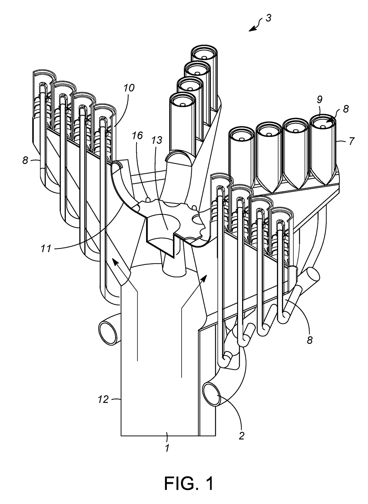
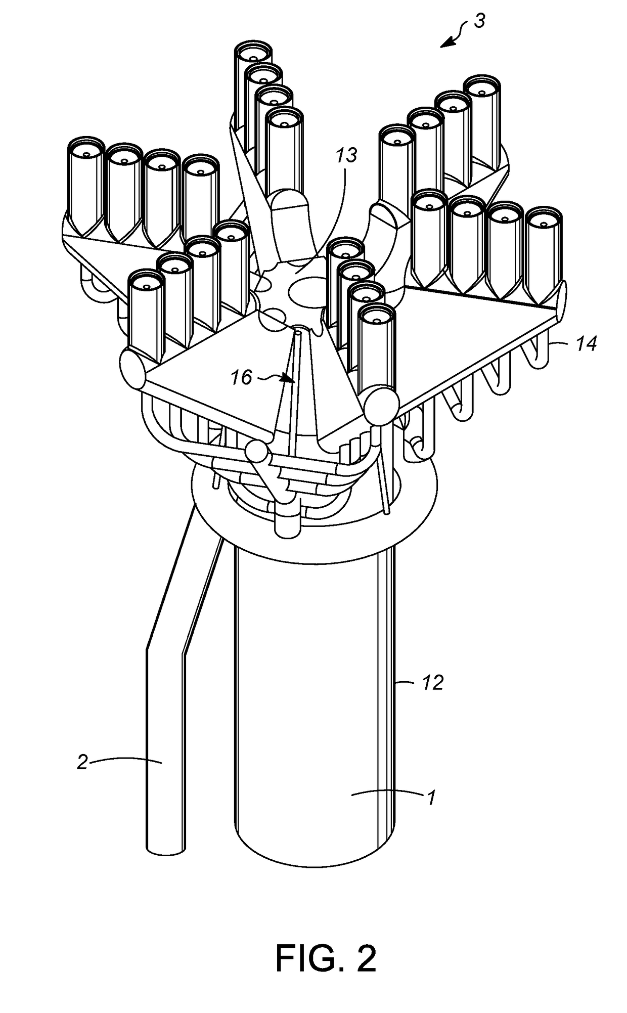
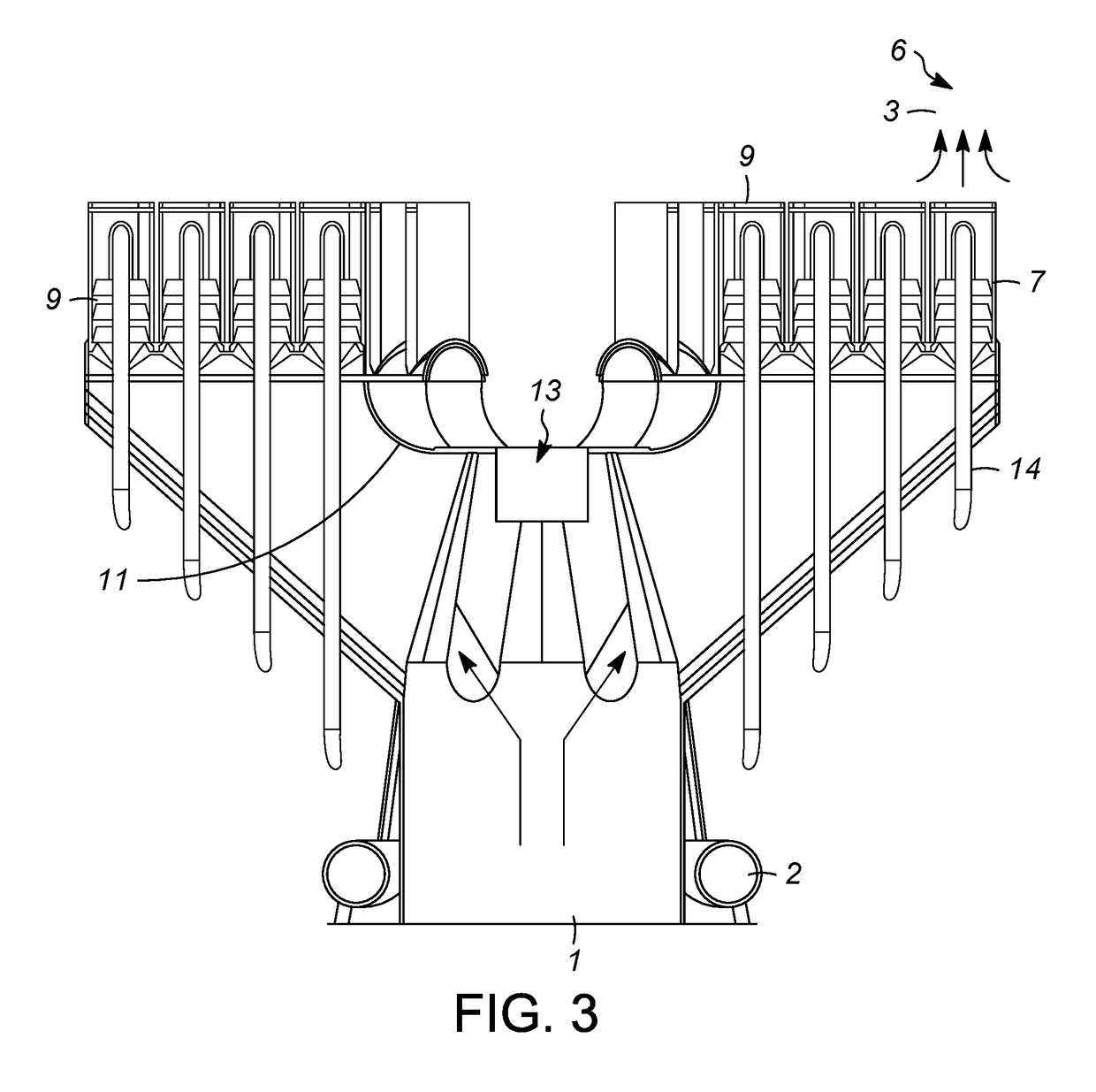
[0032]A first embodiment of the invention is a steam flare comprising a waste gas cylinder connected at an upper portion of the waste as cylinder to a plurality of extensions that extend away from a center of the waste gas cylinder, wherein each of the extensions contain a plurality of flare gas conduits, and wherein a steam tube is located in each of the flare gas conduits. An embodiment of the invention is one, any or all of prior embodiments in this paragraph up through the first embodiment in this paragraph wherein the steam flare further comprises a ring at a top portion of the flare gas conduit and above a top portion of the steam tube. An embodiment of the invention is one, any or all of prior embodiments in this paragraph up through the first embodime...


PUM


Abstract

A steam flare is provided that injects steam, unmixed with air into a waste gas stream at locations where the resulting accelerated steam and waste gas mixture upon exposure to the surrounding air induces a mixture of steam, waste gas and air with improved combustion and effectively complete destruction of the waste gas, and where under low-flow conditions, reduced steam and / or assist gas are required to maintain smokeless operation.

Description

CROSS-REFERENCE TO RELATED APPLICATION[0001]This application claims priority from Provisional Application No. 62 / 559,318 filed Sep. 15, 2017, the contents of which cited application are hereby incorporated by reference in its entirety.BACKGROUND OF THE INVENTION[0002]The present invention relates to an improved flare apparatus and more specifically to an efficient steam-assisted flare apparatus.[0003]Steam assisted flares are used in refinery and petrochemical plants for the combustion of high volume releases of waste gases during interruptions of normal plant operation. The “smokeless” capacity is an extremely important operating parameter. High quantities of high pressure steam is used to entrain atmospheric air and force the mixing of the air with the waste gases. The greater the quantity of air mixed per pound of steam injected with the waste gases the higher the achievable smokeless capacity.[0004]Flare apparatus for burning and disposing of combustible gases are well known. Fl...

Claims


Application Information

Patent Timeline
IPC IPC(8): F23G7/08F23L7/00
CPCF23G7/085F23L7/005F23G5/50F23L5/04F23G2209/14F23L2900/07009F23D14/46
Inventor MARTIN, MATTHEW A.MARTIN, RICHARD R.KRAUS, KURT E.JENNINGS, JAY D.
Owner HONEYWELL INT INC
Learn More