
Method for transferring a stress state (stress sensor) of an FE simulation result to a new FE mesh geometry of a modeled construction system in a simulation chain of production operations

a technology of stress sensor and simulation result, which is applied in the direction of configuration cad, cad techniques, instruments, etc., can solve the problems of unfavorable transferring of stress, undesired shape alterations, and undesired shape alterations

Active Publication Date: 2019-03-21
INNOVATIONSGES FUR FORTGESCHRITTENE PRODN SSYST & DER FAHRZEUGIND
View PDF0 Cites 1 Cited by
  • Summary
  • Abstract
  • Description
  • Claims
  • Application Information

AI Technical Summary

Benefits of technology

The invention allows for better evaluation of component characteristics and manufacturing processes by using stresses in a linked simulation of a production process chain despite different modelings and different FE solvers. This results in improved evaluation of the overall performance of the production process.

Problems solved by technology

Thus, for example, in a virtual production process chain which overlaps subsections, after the transferring of a stress state (stress tensor) from an FE simulation result to a new target FE mesh, with the use of the result in a subsequent FE simulation, undesired shape alterations occur, which can be due to different mesh densities, FE element types and material models.
Since, in conventional methods according to the type mentioned in the introduction, a transferring of stresses within a simulation chain leads to undesired shape alterations, the conventional transferring of stresses is not expedient.

Method used


Image

  • Method for transferring a stress state (stress sensor) of an FE simulation result to a new FE mesh geometry of a modeled construction system in a simulation chain of production operations
  • Method for transferring a stress state (stress sensor) of an FE simulation result to a new FE mesh geometry of a modeled construction system in a simulation chain of production operations
  • Method for transferring a stress state (stress sensor) of an FE simulation result to a new FE mesh geometry of a modeled construction system in a simulation chain of production operations

Examples


Embodiment Construction

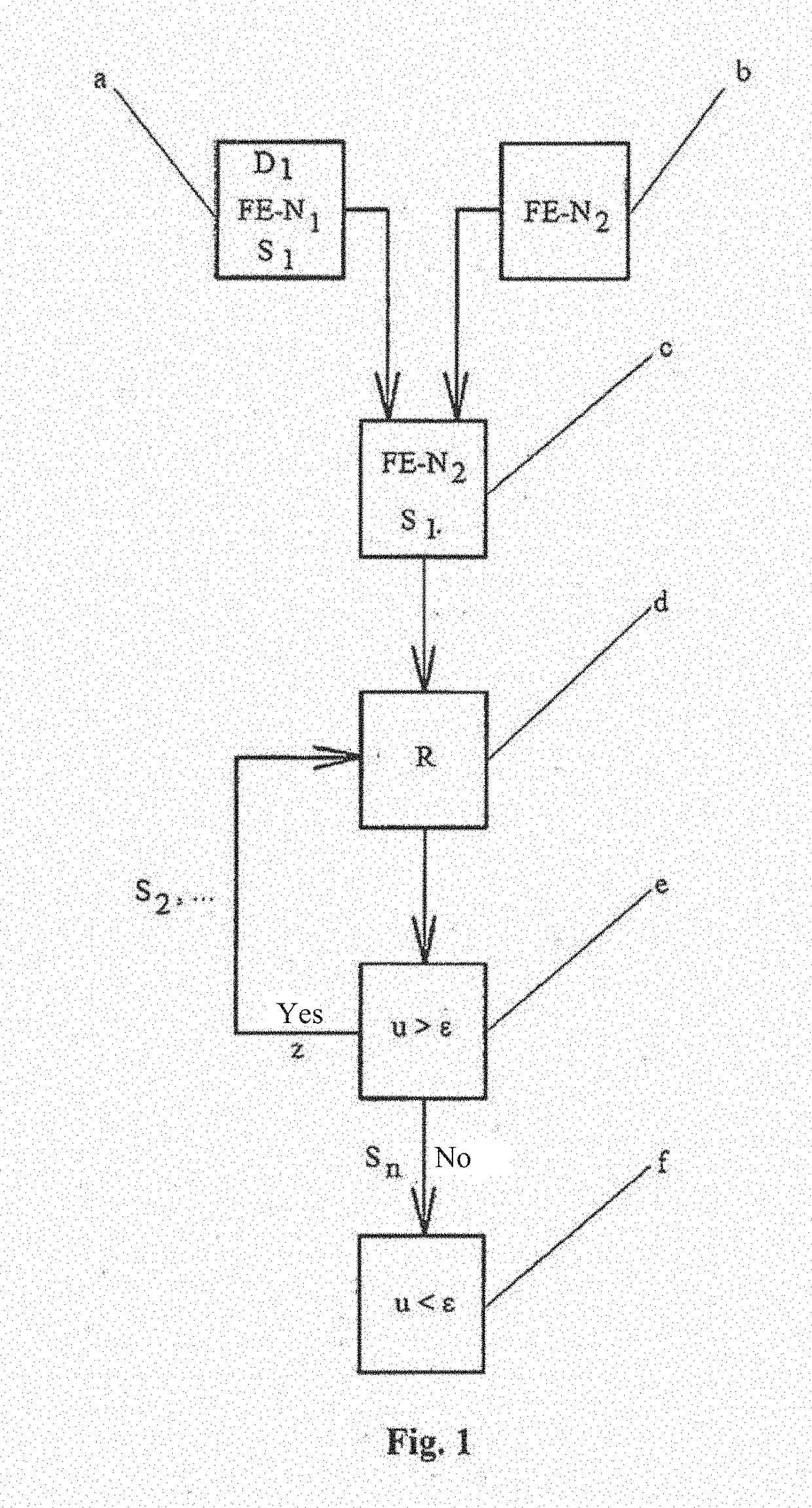
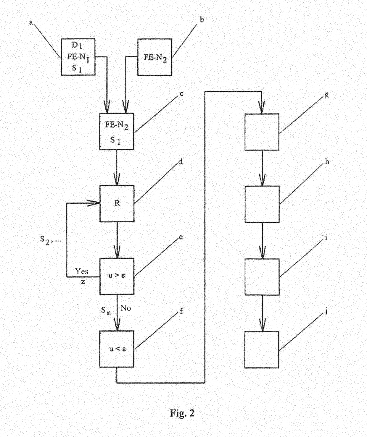
[0039]FIG. 1 shows a block diagram of the method for transferring a stress state (stress tensor) S1 of an FE simulation result FE-N1 of a modeled construction system or component 1 to a newly to be applied FE mesh geometry FE-N2 of the latest in the simulation chain of a production process according to at least one embodiment of the invention.

[0040]Here, in a step a) a first data set D1 is provided, which describes the FE simulation result with a stress state of the FE simulation with the starting FE mesh FE-N1 of the construction system or component 1.

[0041]In a step b) the new FE mesh geometry FE-N2 (new FE target mesh) is applied to the construction system or component 1, which is associated with a second production operation.

[0042]Subsequently, in a step c) the stress state (stress tensor S1) of the first data set D1 provided in step a) is transferred to the new FE mesh geometry FE-N2 of the construction system or component 1 created in step b).

[0043]Thereafter, in a step d) an ...


PUM


Abstract

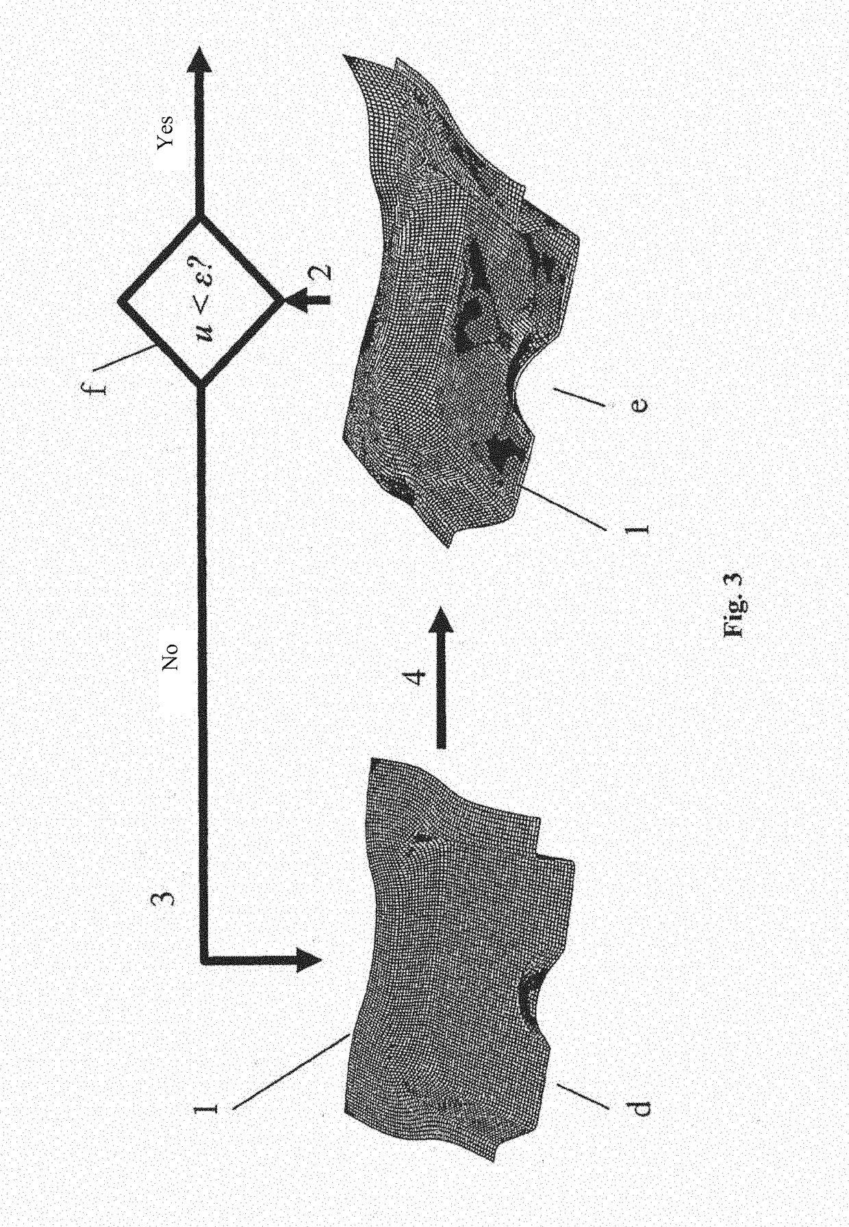
The invention relates to a method for transferring a stress state of an FE simulation result to a new FE mesh geometry of a simulated construction system, such as a component for motor vehicles that has a 3-D shape, in a simulation chain of production operations, comprising: a) providing a first data set, which describes the FE simulation result with a stress state of the FE simulation of the construction system or component of a first production operation, b) creating the new FE mesh geometry of the simulated construction system or component, which new FE mesh geometry is associated with a second production operation, c) transferring the stress state of the provided first data set to the new FE mesh geometry of the construction system or component, d) performing an equilibrium calculation by using the stress tensor in the FE mesh geometry, wherein deformation of the construction system or component results, which deformation differs from the deformation in the FE mesh by a shape alteration u>tolerance value ε, e) iteratively repeating the equilibrium calculation as a cyclic equilibrium iteration in the new FE mesh geometry (in the new target FE mesh) of the construction system or component, wherein, in each cycle, a new stress state is applied to the FE mesh geometry of the construction system or component and stress components that lead to undesired shape alterations are decreased until a displacement / termination criterion of shape alteration u<tolerance value ε is achieved, and f) displaying the fulfilled condition of u<ε.

Description

FIELD OF THE INVENTION[0001]The invention relates to a method for transferring a stress state (stress tensor) of an FE simulation result to a new FE mesh geometry of a modeled construction system such as a component for motor vehicles that has a 3-D shape, in a simulation chain of production operations.BACKGROUND OF THE INVENTION[0002]From DE 10 2012 006 965 A1 the simulating of shaping operations of a composite part having a 3-D shape and an anisotropic layer is known. The shaping operations can be, for example, pressing- and deep drawing operations, which are able to be simulated by means of software solutions available on the market and / or individual software solutions. In particular, software solutions are known which are generally available under the trade names LS DYNA or PAM-FORM. To simulate the shaping operation, the programs are fed with a material which characterizes a blank. In addition, further parameters which relate to a shaping tool and / or similar are provided before...

Claims


Application Information

Patent Timeline
Patent Type & Authority Applications(United States)
IPC IPC(8): G06F17/50
CPCG06F17/5018G06F17/5095G06F2217/02G06F2217/42G06F2217/16G06F30/15G06F2113/22G06F2113/24G06F30/23G06F2111/10G06F2111/20
Inventor NITSCHE, MARTINWESSELS, HERIBERT
Owner INNOVATIONSGES FUR FORTGESCHRITTENE PRODN SSYST & DER FAHRZEUGIND
Learn More