
High efficiency air filter device and operating method thereof

a high-efficiency, air-filter technology, applied in the direction of dispersed particle separation, transportation and packaging, separation processes, etc., can solve the problems of high energy consumption of conventional air-filtration mode, increased dust quantity and thickening, and inability to use air-filters and other problems, to achieve the effect of low energy consumption, high efficiency and ultra-stable structur

Pending Publication Date: 2019-03-28
FOSHAN HUMAN HABITAT ENVIRONMENTAL PROTECTION ENG
View PDF7 Cites 118 Cited by
  • Summary
  • Abstract
  • Description
  • Claims
  • Application Information

AI Technical Summary

Benefits of technology

The present invention provides an air filter that has high efficiency, low energy consumption, ultra stability, and long service life. It is ideal for industrial, commercial, and special occasions such as central air conditioners in clean workshops and offices, hotels, and hospitals. The device can achieve these benefits to provide better air filtration.

Problems solved by technology

When dust is filtered and collected on the outer surface of the filter material, the dust quantity increases and thickens over time, and the resistance of the air filter material continues to increase until it exceeds the rated resistance of the air filter, resulting that the air filter cannot be used and must be replaced with a new air filter unit.
Hence, the total final resistance value of the conventional air filtration mode is generally 1700 Pa, and therefore, the conventional air filtration mode has a defect of high energy consumption.
The total resistance difference of the conventional air filtration mode ranges from 0 to 1500 Pa, resulting that the conventional air filtration mode has disadvantages of the resistance value fluctuating greatly and poor operational stability.

Method used


Image

  • High efficiency air filter device and operating method thereof
  • High efficiency air filter device and operating method thereof

Examples


Embodiment Construction

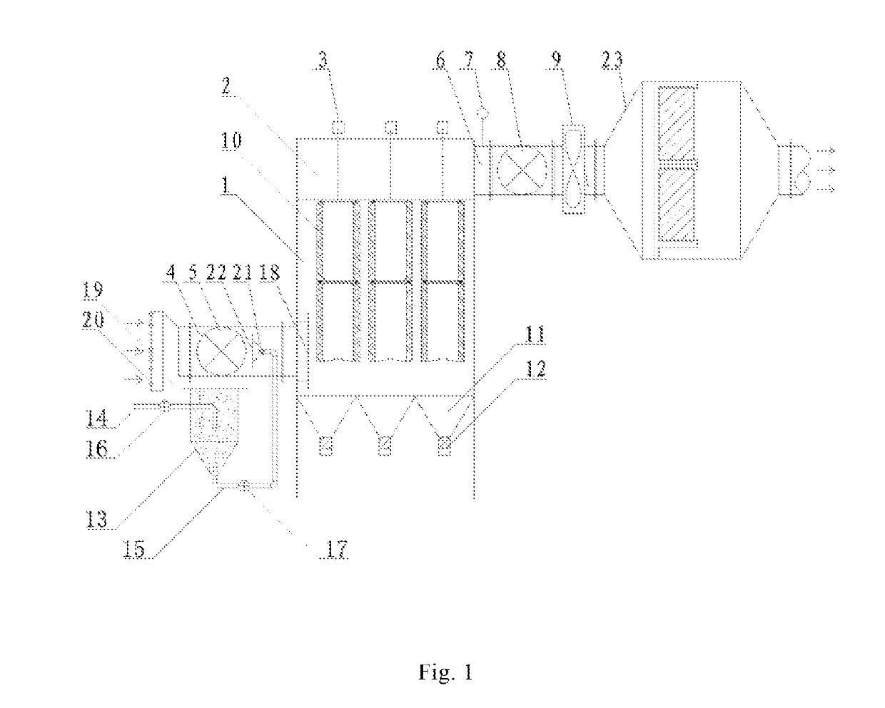
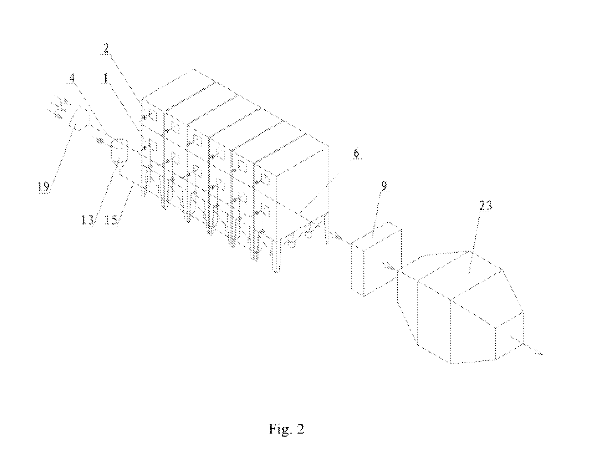
[0038]FIG. 1 is s schematic structural diagram of the present invention. As shown in the figure, the structure includes an air filter system and a powder distribution system. The air filter system includes an air filter chamber 1, a clean air chamber 2, and high-pressure jet pulse powder cleaning devices 3. An entrance of the air filter chamber 1 is in communication with an air inlet pipe 4; an air inlet pipe valve 5 is disposed on the air inlet pipe 4; an exit of the clean air chamber 2 is in communication with an air outlet pipe 6; a pressure detector 7 and an air outlet pipe valve 8 are disposed on the air outlet pipe 6, and the air outlet pipe 6 is in communication with an exhaust fan 9; a plurality of bag filters or filter cartridges 10 are disposed in the air filter chamber 1. An opening end of each of the bag filters or filter cartridges 10 is in communication with the clean air chamber 2, and each of the high-pressure jet pulse powder cleaning devices 3 is disposed above the...


PUM

PropertyMeasurementUnit
Pressureaaaaaaaaaa
Pressureaaaaaaaaaa
Pressureaaaaaaaaaa

Abstract

An air filter device and an operating method thereof. The air filter device comprises an air filter system and a powder distribution system. The air filter system comprises an air filter chamber (1), a clean air chamber (2), and a high-pressure jet pulse powder cleaning device (3). An entrance of the air filter chamber (1) is in communication with an air inlet pipe (4); an exit of the clean air chamber (2) is in communication with an air outlet pipe (6), and the air outlet pipe (6) is in communication with an exhaust fan (9). A plurality of bag filters or filter cartridges (10) are disposed in the air filter chamber (1). An opening end of each of the bag filters or filter cartridges (10) is in communication with the clean air chamber (2), and high-pressure jet pulse powder cleaning devices (3) are disposed above the opening end of the corresponding bag filters or filter cartridges (10). The powder distribution system includes a powder storage tank (13), which is in communication, via a powder delivery tube (15), with the air inlet pipe (4) of the air filter chamber (1). The operating method comprises a first powder distribution step and a second powder distribution step, which are respectively performed according to pressure detection status of the air filter chamber (1).

Description

FIELD OF THE INVENTION[0001]The present invention belongs to the technical field of gas filtering, and in particular, relates to an air filter device and an operating method thereof.BACKGROUND ART[0002]Conventional air filters are generally made up of one or more filter units connected in parallel, and the one or more filter units include consistent materials, filtration accuracy, and geometrical configuration. The air filter unit is generally square, and each square air filter unit is composed of an outer frame, filter material, a fixture, a septum device and a sealing device. Filter materials generally include filter cotton, rayon, polyester synthetic fiber, glass fiber paper or the like, and filter materials generally adopt dense folding structures.[0003]When dust is filtered and collected on the outer surface of the filter material, the dust quantity increases and thickens over time, and the resistance of the air filter material continues to increase until it exceeds the rated r...

Claims


Application Information

Patent Timeline
IPC IPC(8): B01D46/02B01D46/00B01D46/04B01D46/44B01D46/46
CPCB01D46/023B01D46/002B01D46/0026B01D46/04B01D46/446B01D46/46B01D2273/12B01D46/2411B01D46/645B01D46/58B01D46/72B01D46/62B01D46/02B01D46/71F23J2219/60
Inventor HUANG, QINGBAO
Owner FOSHAN HUMAN HABITAT ENVIRONMENTAL PROTECTION ENG
Learn More