Apparatus for dispensing a vapor phase reactant to a reaction chamber and related methods

a technology of reactant and apparatus, which is applied in the direction of coating, chemical vapor deposition coating, metallic material coating process, etc., can solve the problems of undesirable downtime, particular precursors are not readily adaptable to re-charge, and the reaction chamber is not suitable for dispensing

Active Publication Date: 2019-03-28
ASM IP HLDG BV
View PDF2 Cites 251 Cited by
  • Summary
  • Abstract
  • Description
  • Claims
  • Application Information

AI Technical Summary

Benefits of technology

[0010]This summary is provided to introduce a selection of concepts in a simplified form. These concepts are described in further detail in the detailed description of example embodiments of the disclosure below. This summary is not intended to identify key features or essential features of the claimed subject matter, nor is it intended to be used to limit the scope of the claimed subject matter.

Problems solved by technology

However, there are some forms of precursors which are not readily adaptable for re-charge of the chemical ampoule, for example, a particular precursor may be easily degraded or a particular precursor may become strongly attached to the inner surface of the chemical ampoule during the re-charge procedure.
In addition, the exchange of the discharged chemical ampoule for a full chemical ampoule may incur undesirable down time for the semiconductor processing apparatus and may also necessitate the need for safe storage of a large number of chemical ampoules.
However, as the size of the chemical ampoule increases an increased proportion of the heat provided by the belt heater may be undesirably absorbed at the outer surface of the chemical ampoule, thereby producing an undesirable thermal gradient across the chemical ampoule and consequential a deterioration in semiconductor fabrication processes.
In addition to the problems associated with heating a larger chemical ampoule, chemical ampoule upsizing may result in additional processing issues.
This stabilization process may expend valuable processing time and may be referred to as “dummy time.” It has been found that as the volume of the chemical ampoule increases, the “dummy time” required to stabilize the vapor pressure of the precursor inside the chemical ampoule also noticeably increases, thereby wasting costly processing time as well as consuming valuable precursor.
The increase in distance between the carrier gas inlet and the exposed surface of the source chemical can result in an unwanted variation in the vapor phase reactant flow out from the chemical ampoule to the reaction chamber.
For example, as the source chemical is consumed and the distance between the carrier gas inlet and the surface of the source chemical increases, the flow of vapor phase reactant from the chemical ampoule to the reaction chamber may decrease, resulting in an undesirable variation in semiconductor processing conditions.

Method used


Image

  • Apparatus for dispensing a vapor phase reactant to a reaction chamber and related methods
  • Apparatus for dispensing a vapor phase reactant to a reaction chamber and related methods
  • Apparatus for dispensing a vapor phase reactant to a reaction chamber and related methods

Examples


Embodiment Construction

[0019]Although certain embodiments and examples are disclosed below, it will be understood by those in the art that the invention extends beyond the specifically disclosed embodiments and / or uses of the invention and obvious modifications and equivalents thereof. Thus, it is intended that the scope of the invention disclosed should not be limited by the particular disclosed embodiments described below.

[0020]The illustrations presented herein are not meant to be actual views of any particular material, structure, or device, but are merely idealized representations that are used to describe embodiments of the disclosure.

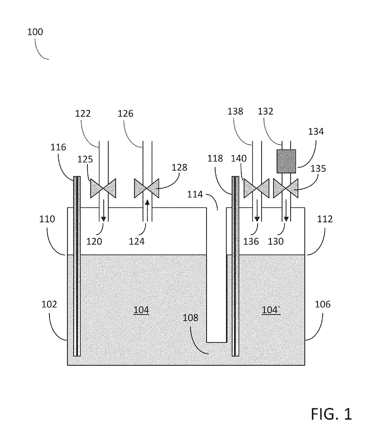
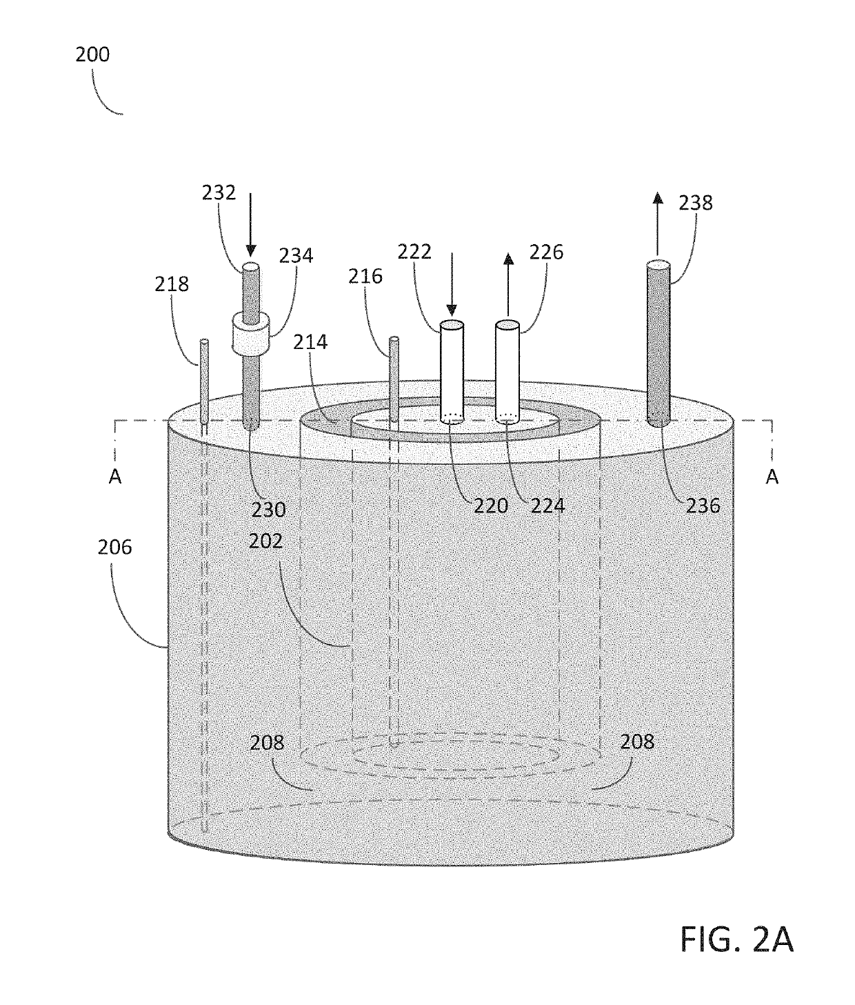
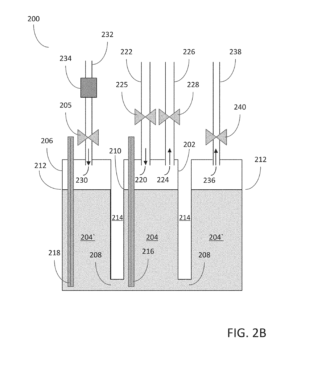
[0021]The embodiments of the disclosure may include apparatus and methods for dispensing a vapor phase reactant to a reaction chamber. In particular, the embodiments of the disclosure may include an apparatus capable of dispensing a highly stable flow of vapor phase reactant to a semiconductor reaction chamber for an extended period of time.

[0022]The problems associate...


PUM

PropertyMeasurementUnit
total volumeaaaaaaaaaa
temperatureaaaaaaaaaa

Abstract

An apparatus for dispensing a vapor phase reactant to a reaction chamber is disclosed. The apparatus may include: a first chamber configured for holding a source chemical with a first fill level; and a second chamber configured for holding the source chemical with a second fill level and in fluid communication with the first chamber via a fluid channel below the first and second fill levels. The apparatus may also include: a second chamber inlet opening in fluid communication with a pressurizing gas feed provided with a flow controller configured for controlling a flow of a pressurizing gas in the second chamber to control the first fill level in the first chamber. Methods for dispensing a vapor phase reactant are also provided.

Description

CROSS-REFERENCE TO RELATED APPLICATION[0001]This application claims the benefit of U.S. Provisional Application No. 62 / 562,112, entitled “Apparatus for Dispensing a Vapor Phase Reactant to a Reaction Chamber and Related Methods” and filed on Sep. 22, 2017, the disclosure of which is hereby incorporated herein for reference.FIELD OF INVENTION[0002]The present disclosure relates generally to an apparatus for dispensing a vapor phase reactant to a reaction chamber and particular an apparatus for dispensing a highly stable flow of vapor phase reactant to a reaction chamber for an extended period of time. The disclosure also includes methods for dispensing a vapor phase reactant to a reaction chamber.BACKGROUND OF THE DISCLOSURE[0003]Semiconductor processing apparatus commonly use one or more vapor phase reactants, i.e., precursors, as source chemicals for performing semiconductor substrate processes, such as, for example, deposition processes, cleaning processes and etching processes. T...

Claims


Application Information

Patent Timeline
Patent Type & Authority Applications(United States)
IPC IPC(8): C23C16/448C23C16/455
CPCC23C16/4481C23C16/45557H01L21/67017H01L21/67011C23C16/45561H01L21/67276H01L21/67253H01L21/67098H01L21/67248H01L21/02312H01L21/02337
Inventor JDIRA, LUCIANTERHORST, HERBERTTSUJI, NAOTOSUSA, YOSHIO
Owner ASM IP HLDG BV
Why Eureka
Try Eureka