Robot system

a robot and system technology, applied in the field of robot systems, can solve the problems of increasing the size of the device, reducing the loading weight, limiting the movable range of the robot, etc., and achieve the effect of improving work efficiency

Active Publication Date: 2019-03-28
SEIKO EPSON CORP
View PDF0 Cites 10 Cited by
  • Summary
  • Abstract
  • Description
  • Claims
  • Application Information

AI Technical Summary

Benefits of technology

[0027]With this configuration, a work efficiency can

Problems solved by technology

In general, a device to be attached to the robot arm limits a movable range of a robot or reduces a loading weight of the robot as the size becomes larger.
Therefore, in the device described in JP-A-2014-89062, a circuit for contr

Method used


Image

  • Robot system
  • Robot system
  • Robot system

Examples


first embodiment

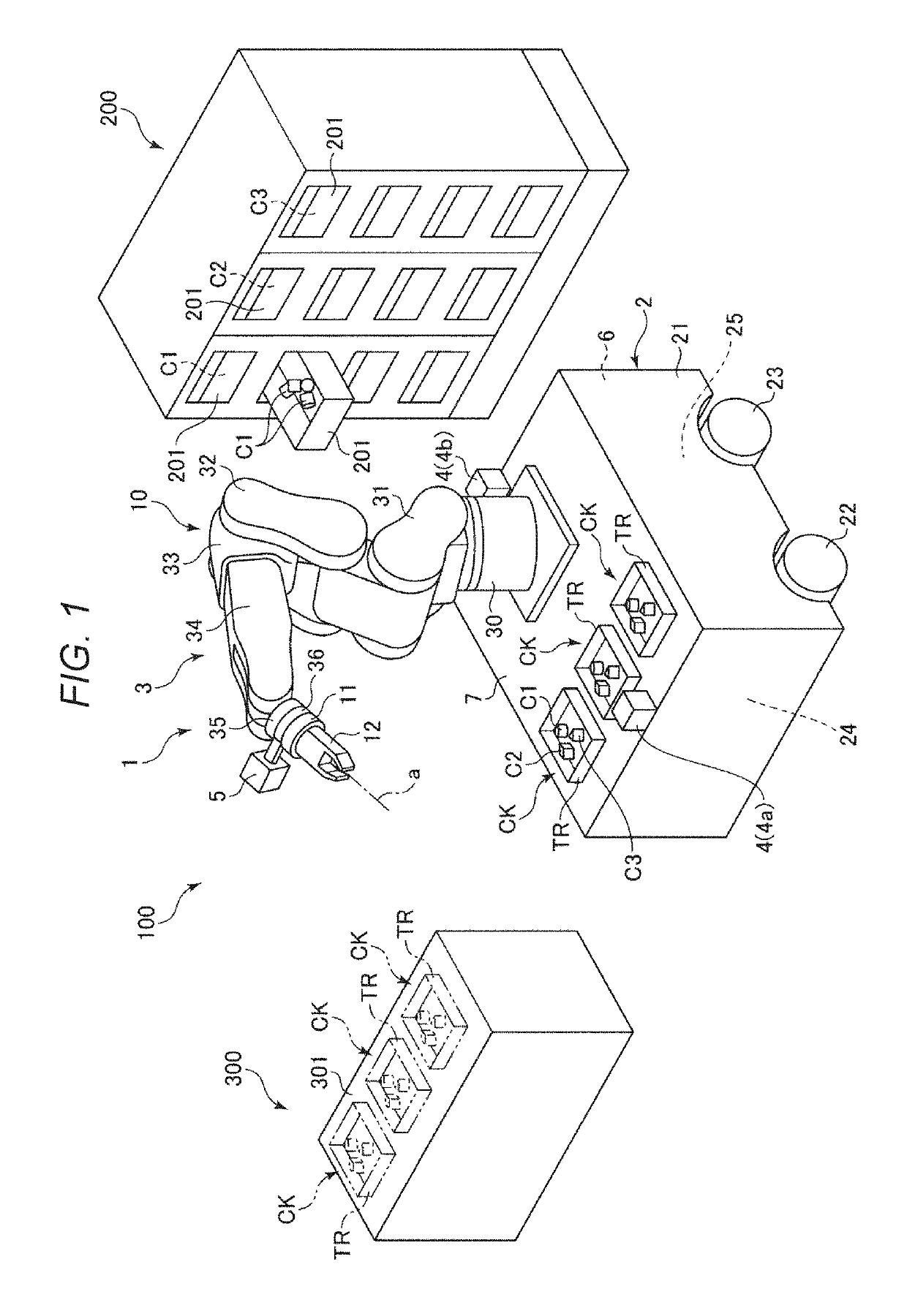
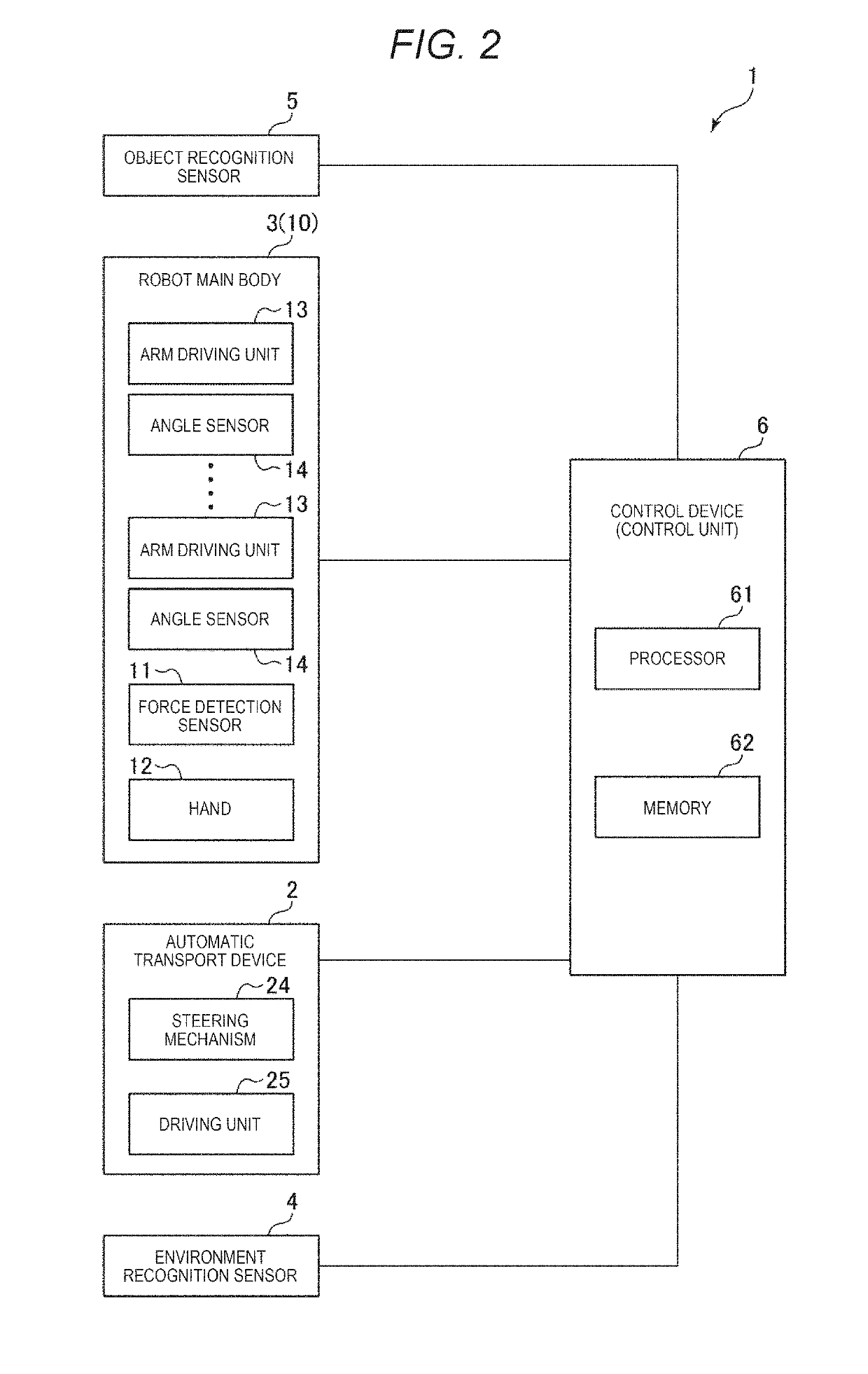
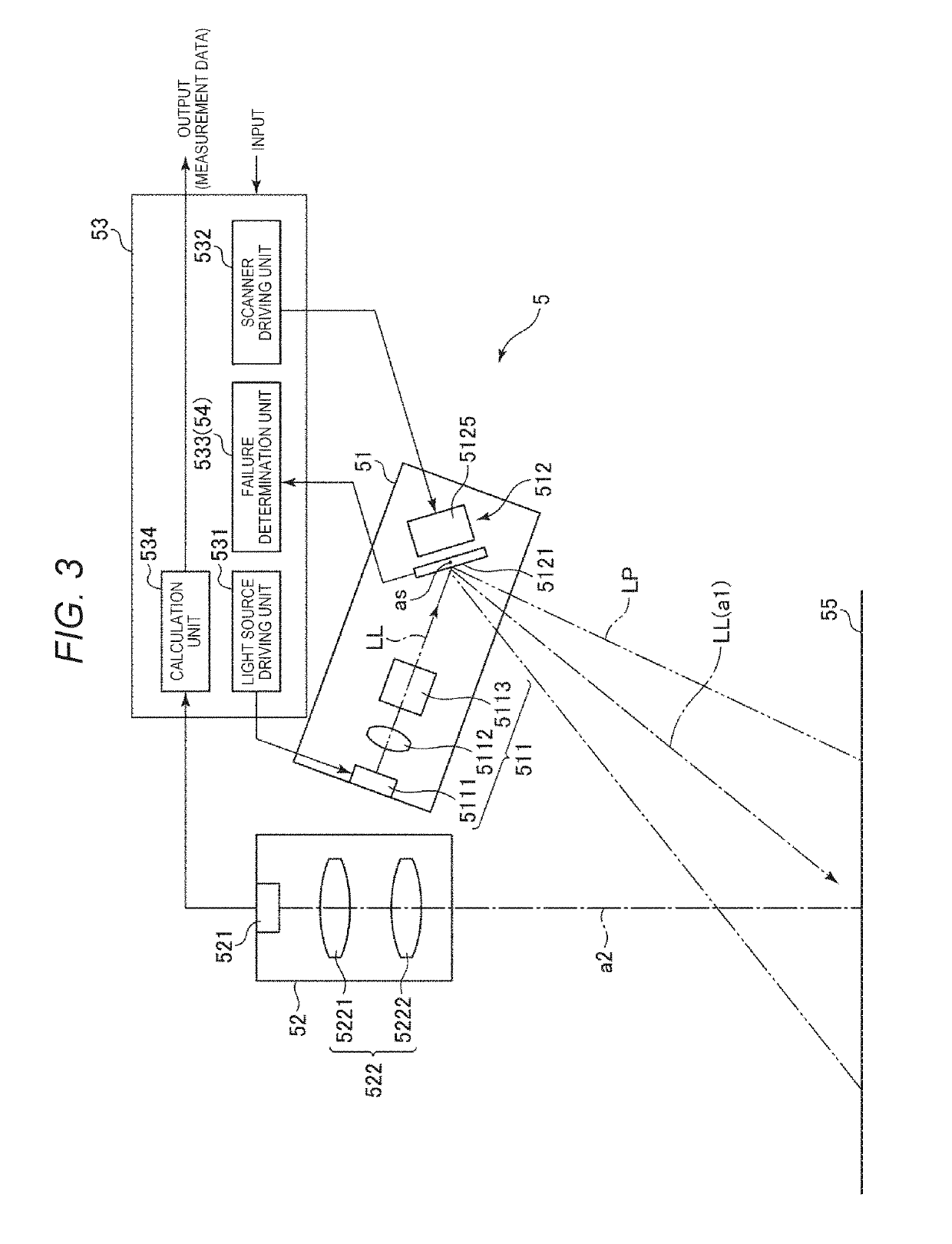
[0048]FIG. 1 is a perspective view schematically illustrating a robot system according to a first embodiment of the invention. FIG. 2 is a block diagram illustrating a control system of the robot system illustrated in FIG. 1. FIG. 3 is a schematic view of an object recognition sensor included in the robot system illustrated in FIG. 1. FIG. 4 is a view illustrating a bright and dark state of a projection pattern (pattern light) generated by a projection device included in the object recognition sensor illustrated in FIG. 3. FIG. 5 is a perspective view of an optical scanner included in the object recognition sensor illustrated in FIG. 3. FIG. 6 is a view illustrating a waveform of a driving signal from a scanner driver included in the object recognition sensor illustrated in FIG. 3. FIG. 7 is a view illustrating a waveform (lower part in the drawing) of a modulating signal output from a light source driver of the object recognition sensor illustrated in FIG. 3, and a deflection angle...

second embodiment

[0145]FIG. 18 is a perspective view illustrating a robot used in a robot system according to a second embodiment of the invention.

[0146]The embodiment is the same as the above-described first embodiment except that the invention is applied to a dual arm robot. Hereinafter, the second embodiment will be described focusing on differences from the above-described embodiments, and the description of similar matters will be omitted.

[0147]The robot system 100A includes: an automatic transport device 2A; a robot main body 3A which has two robot arms 10A mounted on the automatic transport device 2A; the environment recognition sensor 4 which is disposed in the automatic transport device 2A; the object recognition sensors 5 (shape measurement devices) which are disposed respectively in the automatic transport device 2A and each of the robot arms 10A; a control device 6A (control unit) which controls operations of the automatic transport device 2A and each of the robot arms 10A; and a placing...


PUM


Abstract

A robot system including: one or two robot arms which perform work on a target; a shape measurement device which is disposed on the robot arm and measures a shape of the target; and a controller which controls the robot arm based on the shape measurement device, in which the shape measurement device includes a projection device which projects striped pattern light onto the target, an image capturing unit which captures the image of the pattern light, and a processor which calculates the shape of the target based on the captured image by the image capturing device, and in which the projection device includes a light source device which emits linear laser, an optical scanner which generates the pattern light by reflecting the laser from the light source device and by scanning the target, and a scanner driver which outputs a driving signal to drive the optical scanner non-resonantly.

Description

BACKGROUND1. Technical Field[0001]The present invention relates to a robot system.2. Related Art[0002]As a robot system which performs work with respect to a target using a robot having a robot arm, a system in which a device for measuring the shape of the target is attached to the robot arm, and the robot arm is operated using the measurement result of the device to perform the work is known.[0003]A device for measuring the shape of the target projects a bright and dark pattern onto the target and measures the shape of the target by a phase shift method as described in JP-A-2014-89062. Here, the device described in JP-A-2014-89062 projects the bright and dark pattern onto the target by performing scanning with light from a laser light source by a MEMS mirror that swings in a resonance.[0004]In general, a device to be attached to the robot arm limits a movable range of a robot or reduces a loading weight of the robot as the size becomes larger. Therefore, reduction in size is requir...

Claims


Application Information

Patent Timeline
IPC IPC(8): G01B11/25B25J9/16B25J13/08B25J19/02
CPCG01B11/254B25J9/1697B25J13/087B25J19/022B25J9/12B25J9/161G05B19/401G05B2219/37555G05B2219/37571G05B2219/40564
Inventor WAKABAYASHI, SHUICHIHINO, MAKIKOMIZOGUCHI, YASUSHI
Owner SEIKO EPSON CORP
Why Eureka
Try Eureka