Flat Cable

a technology of flat cable and cable body, which is applied in the direction of insulating conductor/cable, cable, insulating conductor/cable, etc., can solve problems affecting the use of products

Active Publication Date: 2019-03-28
AMPHENOL ELECTRONICS ASSEMBLY XIAMEN CO LTD
View PDF6 Cites 14 Cited by
  • Summary
  • Abstract
  • Description
  • Claims
  • Application Information

AI Technical Summary

Benefits of technology

[0018]Compared with the prior art, in the flat cable according to the present invention, the insulating layer is integrally formed or the splicing portion is disposed on the upper surface or the lower surface of the signal unit set. Since the length of the overlapping bonding portion can be set as req

Problems solved by technology

During use, it is likely to cause the insulating film to be easily peeled off, re

Method used


Image

  • Flat Cable
  • Flat Cable
  • Flat Cable

Examples


first embodiment

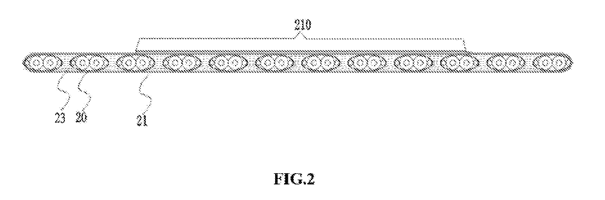
[0030]As shown in FIG. 2, a schematic diagram of the flat cable according to the present invention is shown. The flat cable according to the present invention includes signal unit sets and the insulating film 21 for wrapping and fixing the signal unit set. The unit set includes at least two signal units 20 arranged substantially on the same plane at an interval or side by side. The insulating layer is formed by insulating film 21, the insulating film 21 warps the entire lower surface of the signal unit set and extends from both sides of the lower surface of the signal unit set to the upper surface of the signal unit set, and the two ends of the insulating film 21 are spliced and bonded together. The insulating film 21 and the signal unit 20 are adhesively fixed by an adhesive, and the insulating film 21 of the upper surface and lower surface are not in contact with each other. The adhesive includes (but are not limited to) polyesters, polyimides, polyamide-imides, teflon, polypropyl...

second embodiment

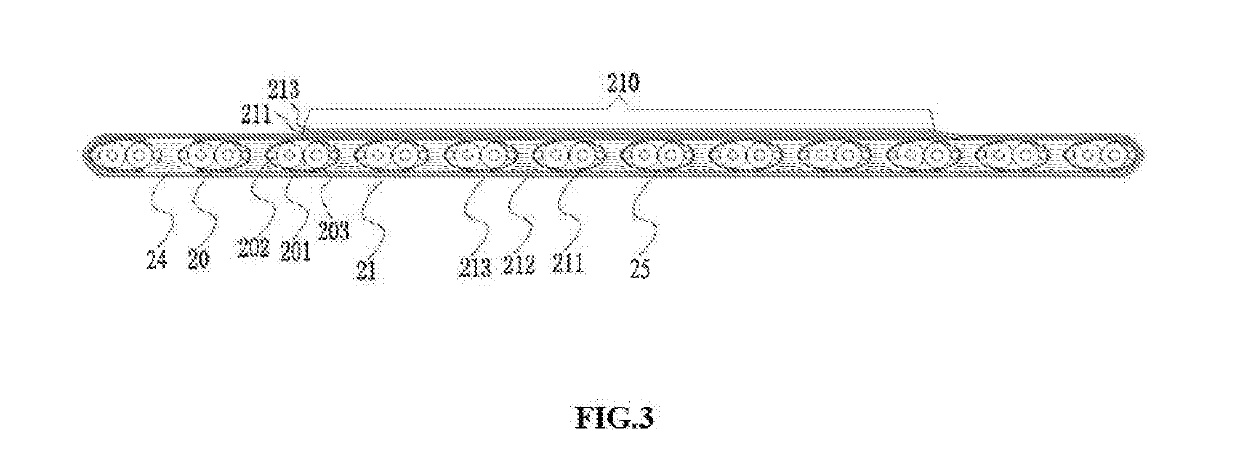
[0034]Further, referring to FIG. 3, a schematic diagram of the flat cable according to the present invention is shown. In order to transmit high-speed signals, the signal unit 20 in the cable can be differential signal unit. The differential signal unit includes the first core line 201, the first earth line 202 and the first shielding insulating film 203 warping the first core line 201 and the first earth line 202. The first core line 201 comprises two first core wires, each of the first core wire comprises a conductor and a longitudinal insulator wrapping the conductor. The shielding and insulation of the differential signal unit are achieved by the first shielding insulating film 203, and the first shielding insulating film 203 is preferably an aluminum foil layer. According to the requirements, the signal unit in the signal unit set further includes the control signal unit 25. And the arrangements between the differential signal unit and the control signal unit are random in the ...

sixth embodiment

[0040]Referring to FIG. 8, the present invention is shown. In the embodiment, the insulating layer is integrally extrusion-injection-molded, so that the signal unit 40 is wrapped by the integrated insulating layer 41, the signal unit set can be isolated through the insulating layer. In addition, the insulation layer can also be replaced with plastic coating.

[0041]Referring to FIG. 9 and FIG. 10, a seventh embodiment of the present invention is shown in FIG. 9, and a hot press molding process of FIG. 9 is shown in FIG. 10. In the seventh embodiment, the insulating layer is an insulating plastic sleeve 51, and the signal unit 50 is arranged side by side in the insulating plastic sleeve 51. After hot press molding, the hot-pressed plastic sleeve is directly formed the adhesive layer on the signal unit. Referring to FIG. 10, the broken line 510 refers to the sleeved thin sleeve before the hot press molding, the solid line 511 is the adhesive layer formed after hot pressing.


PUM


Abstract

The present invention discloses a flat cable, which comprises signal unit sets and the insulating layer which wraps and fixes the signal unit set. The signal unit set is formed by at least two signals units arranged substantially on the same plane at an interval or side by side. The left and right sides of the signal unit set are directly wrapped by insulating layers. The insulating layer is formed by splicing and bonding at least one insulating film, and the splicing points at two ends of the insulating film are located on the upper side or the lower side of the signal unit set. In the flat cable of the present invention, the length of the overlapping portion can be set as required, effectively preventing the phenomenon such as insulating film tear and short circuit caused by insulating film tear.

Description

CROSS REFERENCE TO RELATED APPLICATIONS[0001]This application is based on upon and claim priority to Chinese Patent Application CN 201710866491.1 filed on Sep. 22, 2017, the entire content of which is incorporated herein by reference.TECHNICAL FIELD[0002]The present invention belongs to the field of communication wires, in particular to a flat cable.BACKGROUND[0003]Referring to FIG. 1, in the prior art, the flat cable generally includes the signal unit set 10 formed by arranging a plurality of signal units 101 on the same plane. The upper and lower surfaces of the signal unit set 10 are covered with insulating films 11, 12. The upper and lower insulating films 11, 12 are laterally extended by a small length on both sides of the signal unit set, and are bonded to each other. Recently, based on the considerations of width of the wire and aesthetics, the width of the small extension is generally less than 1 mm. During use, it is likely to cause the insulating film to be easily peeled o...

Claims


Application Information

Patent Timeline
IPC IPC(8): H01B7/08H01B7/02H01B13/06H01B13/14H01B11/00
CPCH01B7/0838H01B7/0807H01B7/0275H01B13/06H01B13/14H01B11/002H01B7/0045H01B7/02H01B7/0861H01B11/00H01B11/203
Inventor HUANG, ZHIMINGYANG, WENCHULI, BILUCHEN, ZHIWEIYE, YIN
Owner AMPHENOL ELECTRONICS ASSEMBLY XIAMEN CO LTD
Why Eureka
Try Eureka