
Polished-rod thermal imaging system for preventing failures in the operation of a sucker rod pump

a technology of thermal imaging system and sucker rod pump, which is applied in the direction of optical radiation measurement, survey, and wellbore/well accessories, etc., can solve the problems of inability to accurately measure the pressure of increase the temperature, and the sucker rod pump is easily damaged, and achieves the effect of reducing calibration and operator intervention, and being convenient to install and opera

Active Publication Date: 2019-04-04
GASOLINEOG AUTOMATION
View PDF2 Cites 4 Cited by
  • Summary
  • Abstract
  • Description
  • Claims
  • Application Information

AI Technical Summary

Benefits of technology

The present invention provides a method for accurately sensing the temperature of different parts of a polished rod using a thermal camera. Additionally, data is gathered from a visible light camera and used to accurately assign temperature values to the different sections of the polished rod using a high performance microcontroller. The aim is to provide a method that can be easily installed and operated with minimal calibration and operator intervention.

Problems solved by technology

Excessive tightness of the sealing gland.
Lack of well fluid at the top of the well.
All the above mentioned conditions cause strain, wearing and eventually an increase of temperature in the stuffing box sealing gland that divert the produced fluids out of the pumping tee into the flowline.
If the root cause of the problem causing a temperature increase in the polished rod is not identified and corrected, and once the sealing gland is damaged, the production fluids will escape out of the pumping tee.
These methods are, in general inaccurate and in particular:
Manpower and vehicles operating costs.

Method used


Image

  • Polished-rod thermal imaging system for preventing failures in the    operation of  a sucker rod pump
  • Polished-rod thermal imaging system for preventing failures in the    operation of  a sucker rod pump
  • Polished-rod thermal imaging system for preventing failures in the    operation of  a sucker rod pump

Examples


Embodiment Construction

[0037]The following is a detailed description of exemplary embodiments to illustrate the principles of the invention. The embodiments are provided to illustrate aspects of the invention, but the invention is not limited to any embodiment. The scope of the invention encompasses numerous alternatives, modifications and equivalent; it is limited only by the claims.

[0038]Numerous specific details are set forth in the following description in order to provide a thorough understanding of the invention. However, the invention may be practiced according to the claims without some or all of these specific details. For the purpose of clarity, technical material that is known in the technical fields related to the invention has not been described in detail so that the invention is not unnecessarily obscured.

Definitions—As used herein:

A. Microcontroller—Refers without limitation to any microprocessor design that preferably emphasizes high integration, low power consumption, self-sufficiency and...


PUM


Abstract

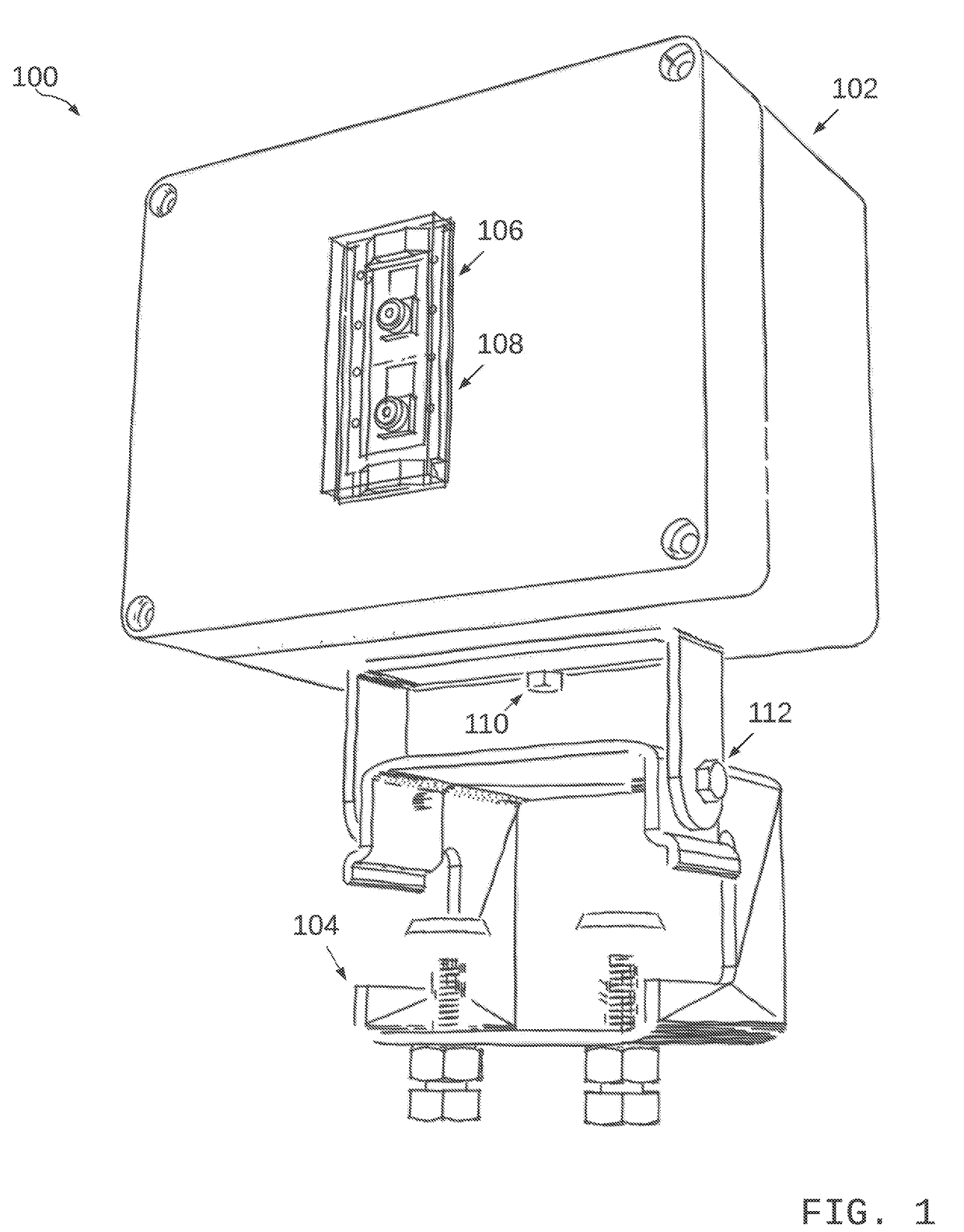
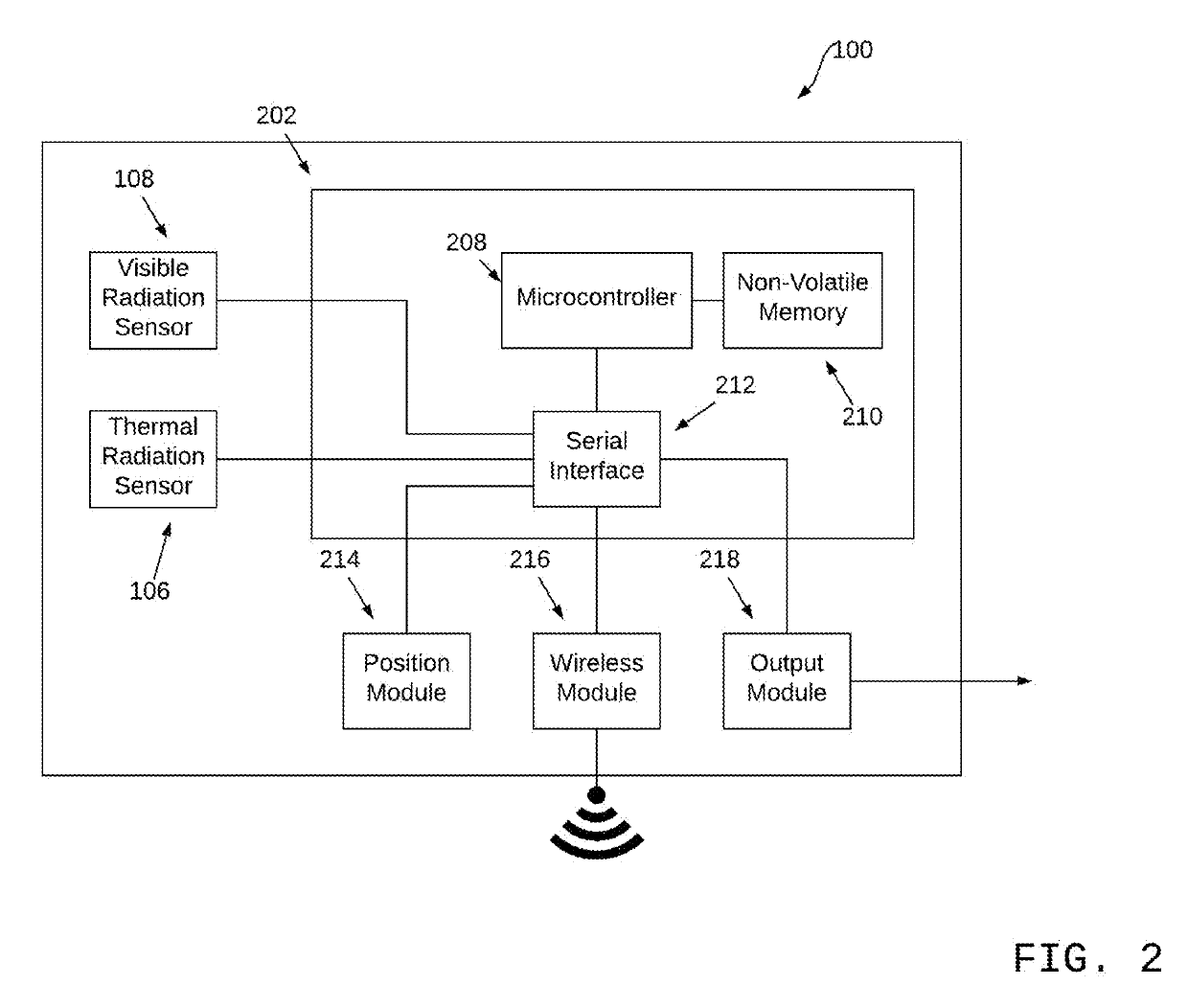
A device for detecting temperatures of a rod on a well having a housing ; a clamp to secure the housing to a post of the well; a thermal radiation sensor secured to the front end of the housing; a visual radiation sensor secured to the front end of the housing, the visual radiation sensor is vertically aligned with the thermal radiation sensor; a microcontroller system placed inside housing, the microcontroller system includes a microcontroller, a non-volatile memory, and a serial interface in electronic communication; a position device placed inside the housing; a wireless device placed inside the housing; output device placed in the interior cavity of the housing; the microcontroller is in electronic communication with the serial interface for communicating with the visible radiation sensor, the thermal radiation sensor, the output module, the wireless module, and the position module.

Description

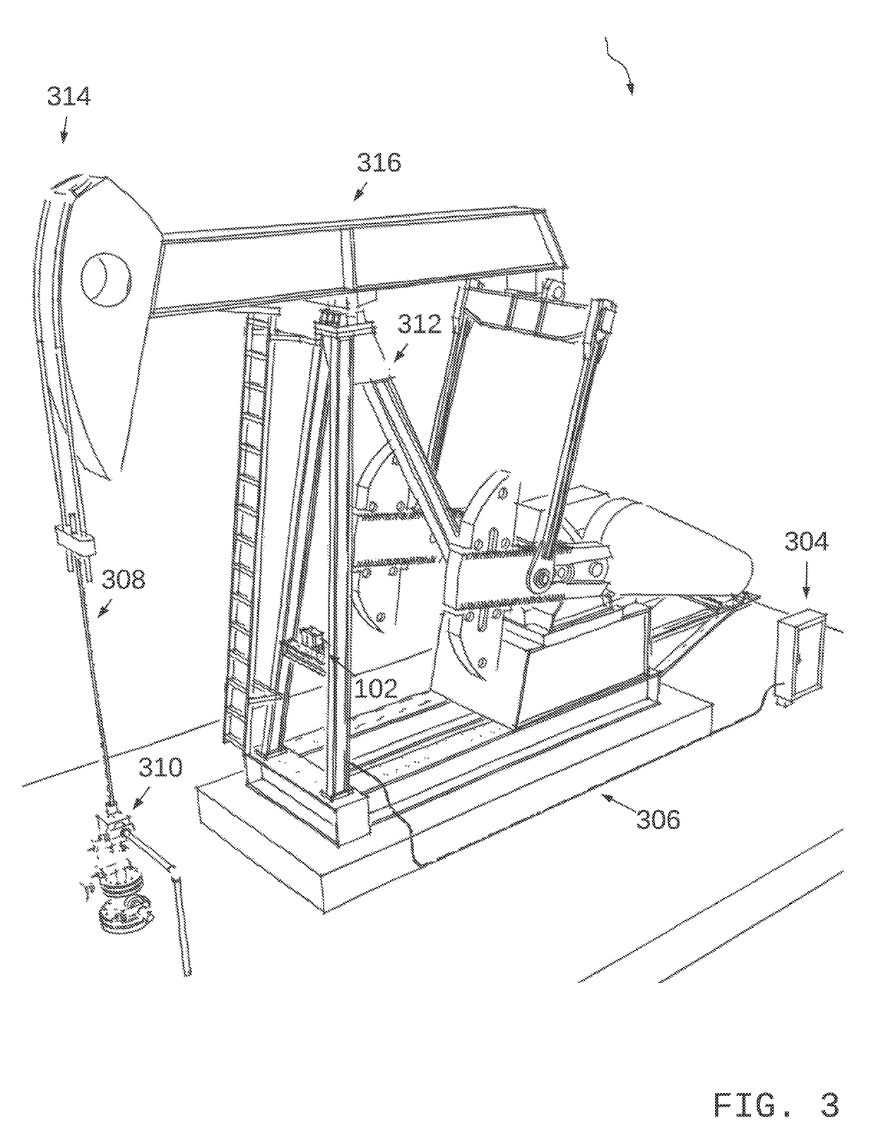
FIELD OF INVENTION[0001]The present invention relates to the general field of hydrocarbons production. More specifically, the present invention relates to a system that prevents failures in the operation of a sucker rod pump.BACKGROUND OF THE INVENTION[0002]Hydrocarbons are often produced from well bores by sucker rod pumps. Beam pumping, or the sucker-rod lift method, is the oldest and most widely used type of artificial lift for most wells. A sucker-rod pumping system is made up of several components, some of which operate aboveground and other parts of which operate underground, down in the well. The surface-pumping unit, which drives the underground pump, consists of a prime mover (usually an electric motor) and, normally, a beam fixed to a pivotal post. The post is called a Sampson post, and the beam is normally called a walking beam. This system allows the beam to rock back and forth, moving the downhole components up and down in the process. The entire surface system is run b...

Claims


Application Information

Patent Timeline
Patent Type & Authority Applications(United States)
IPC IPC(8): E21B47/00G01J5/00G01J5/10G01B11/00H04N5/33G06T7/73G06T7/13
CPCE21B47/0008G01J5/0003G01J5/10G01B11/002H04N5/33G06T7/74G06T7/13E21B47/0002E21B43/127G01J2005/0077G01V8/00G06T2207/10048G06T2207/30181G06T7/0006G06T2207/10016G06T2207/20081G06T2207/30136G06T2207/30164G06T7/73G06T7/12G06T7/174G01J5/026E21B47/009E21B47/002
Inventor CHAVEZ RICO, CESAR AUGUSTOLABRADO MENDIAS, CARLOS ANDREE
Owner GASOLINEOG AUTOMATION
Learn More