
Optical sensor

Active Publication Date: 2019-04-04
DENSO CORP
View PDF0 Cites 0 Cited by
  • Summary
  • Abstract
  • Description
  • Claims
  • Application Information

AI Technical Summary

Benefits of technology

The patent aims to provide an optical sensor that can accurately detect the direction in which light is coming from.

Problems solved by technology

Therefore, there is a concern that a detection accuracy of the directional characteristic may be insufficient.

Method used


Image

  • Optical sensor
  • Optical sensor
  • Optical sensor

Examples


first embodiment

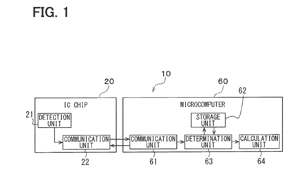
[0019]Hereinafter, a first embodiment of the present disclosure will be described with reference to the drawings. The optical sensor according to the present embodiment is mounted on a vehicle and is used for, for example, detecting light from the exterior of the vehicle and incident on the vehicle. As shown in FIG. 1, the optical sensor 10 includes an IC chip 20 and a microcomputer 60 (hereinafter referred to as microcomputer 60).

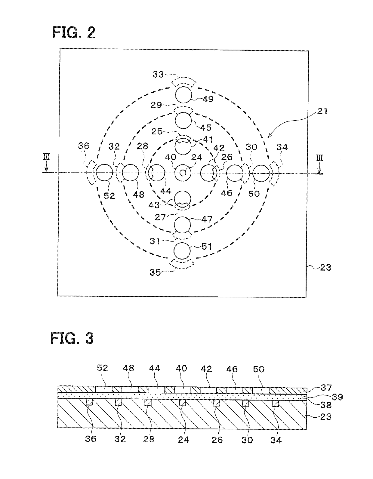
[0020]The IC chip 20 includes a detection unit 21 and a communication unit 22. The detection unit 21 forms a sensing unit for detecting light. As shown in FIGS. 2 and 3, the detection unit 21 includes a semiconductor substrate 23, multiple detection elements 24 to 36, and a light shielding portion 37.

[0021]The multiple detecting elements 24 to 36 are light receiving elements for detecting light. Specifically, each of the detection elements 24 to 36 is a photodiode configured to detect the intensity of the received light. For example, the photodiode is manu...

second embodiment

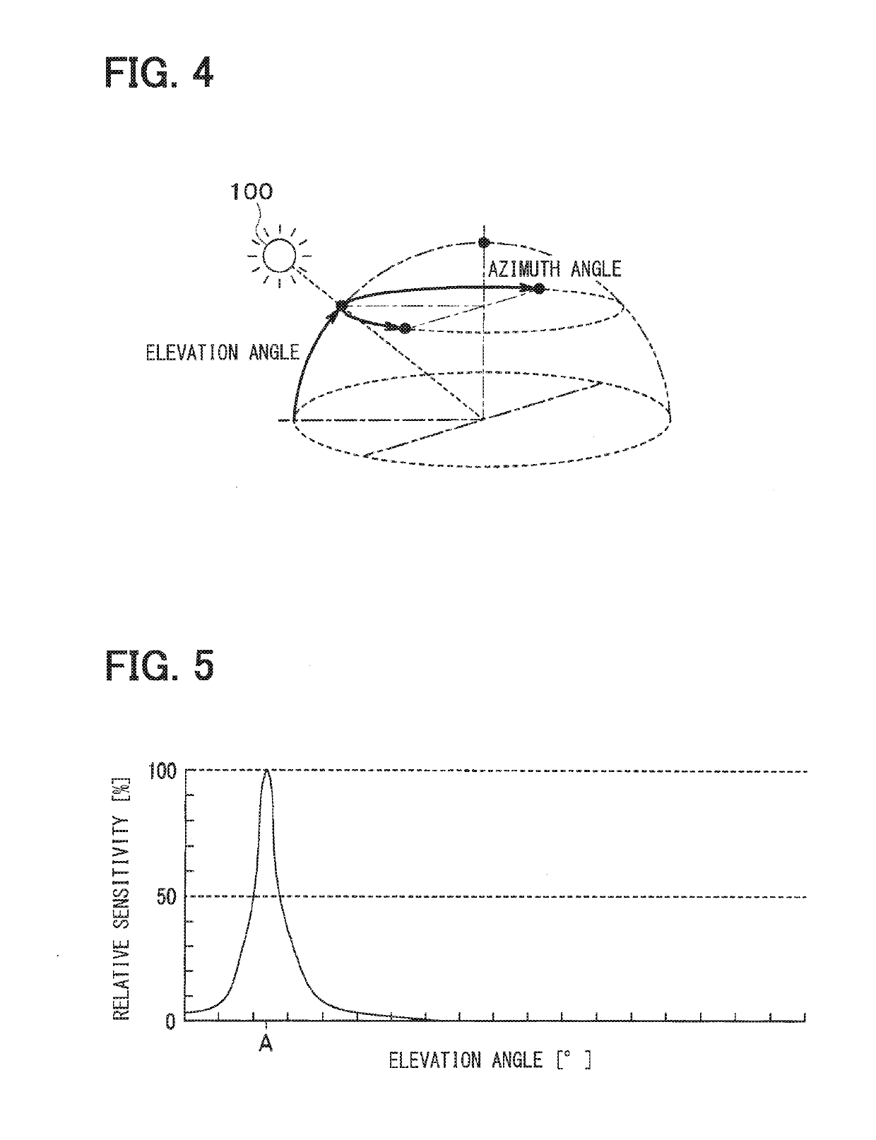
[0056]In the present embodiment, configurations different from those of the first embodiment will be described. In the present embodiment, the storage unit 62 stores multiple reference distributions for respective reference lights having multiple reference directional characteristics respectively. For example, in addition to the reference distribution corresponding to the reference directivity characteristic at the elevation angle A, the storage unit 62 stores the reference distribution corresponding to the reference directivity characteristic at another elevation angle. In addition, the storage unit 62 stores correction coefficients for removing unnecessary light contained in the reference distribution for respective reference distributions correspondingly to the directions of incidence of light to the detection unit 21.

[0057]In response to a request from the external device, the determination unit 63 inputs from the storage unit 62 the reference distribution corresponding to the d...

third embodiment

[0058]In the present embodiment, configurations different from those of the first and second embodiments will be described. In the above-described embodiments, the calculation unit 64 has the function to correct the reference distribution by using the correction coefficient. To the contrary, in the present embodiment, the correction coefficient is not stored in the storage unit 62. Therefore, the determination unit 63 has a function to input a detection signal via the communication units 22 and 61 and to acquire a detection distribution of the intensity of light received with the detection unit 21. The determination unit 63 further has a function to acquire the reference distribution from the storage unit 62.

[0059]The calculation unit 64 inputs the reference distribution and the detection distribution from the determination unit 63, calculates the deviation of the detection distribution from the reference distribution, and obtains the directivity characteristic of the received light...


PUM


Abstract

A detection unit includes multiple detection elements, which are configured to output intensities of received light as detection signals, and a light shielding portion, which is configured to regulate an incident angle of light with respect to the detection elements. The storage unit is configured to store a reference distribution indicating a distribution of intensity of light detected with the detection units caused by irradiation of reference light having a reference directivity characteristic on the detection unit. The calculation unit is configured to input the detection signals from the detection elements, to calculate the detection distribution of the intensity of received light, to input the reference distribution from the storage unit, to calculate a deviation of the detection distribution from the reference distribution, and to calculate a directivity characteristic of received light on the basis of the deviation.

Description

CROSS REFERENCE TO RELATED APPLICATION[0001]This application is based on Japanese Patent Application No. 2016-127869 filed on Jun. 28, 2016, the disclosure of which is incorporated herein by reference.TECHNICAL FIELD[0002]The present disclosure relates to an optical sensor.BACKGROUND ART[0003]Conventionally, for example, Patent Document 1 proposes an optical sensor device including multiple first light receiving elements and a singular second light receiving element having a light receiving area larger than that of each of the first light receiving elements. The multiple first light receiving elements are arranged around the second light receiving element and are different from each other in elevation angle of light to be detected. The second light receiving elements are configured to receive light incident from various directions.[0004]The optical sensor device compares intensities of output signals from the first light receiving elements. In this way, the optical sensor device spe...

Claims


Application Information

Patent Timeline
IPC IPC(8): G01J1/42G01J1/06H01L31/167H01L31/0216
CPCG01J1/42G01J1/06H01L31/167H01L31/02164G01J1/02G01J1/0266G01J1/4228G01J1/1626
Inventor OKURA, TAKAMITSU
Owner DENSO CORP
Features
  • Generate Ideas
  • Intellectual Property
  • Life Sciences
  • Materials
  • Tech Scout
  • Unparalleled Data Quality
  • Higher Quality Content
  • 60% Fewer Hallucinations
Learn More