
Variable valve timing apparatus and method of detecting valve phase thereof

a variable valve timing and valve phase technology, applied in the direction of electrical control, process and machine control, instruments, etc., can solve the problems of increasing the computational load for calculating the valve timing, affecting and affecting the control accuracy of variable valve timing. , to achieve the effect of ensuring the accuracy of detecting the actual valve timing

Active Publication Date: 2009-10-15
TOYOTA JIDOSHA KK +1
View PDF4 Cites 24 Cited by
  • Summary
  • Abstract
  • Description
  • Claims
  • Application Information

AI Technical Summary

Benefits of technology

[0032]Therefore, a main advantage of the present invention is that in the variable valve timing apparatus, the accuracy of detecting actual valve timing can be ensured without excessively increasing computational load, in response to the variation in engine speed.
is that in the variable valve timing apparatus, the accuracy of detecting actual valve timing can be ensured without excessively increasing computational load, in response to the variation in engine speed.

Problems solved by technology

A hydraulic variable valve timing apparatus has a problem that control accuracy of variable valve timing deteriorates in cold climates or at the start of engine operation, as the hydraulic pressure decreases or response of hydraulic control slows down.
On the contrary, when the engine speed is low, particularly when the engine is stopped or the engine is in a low rotation range where the engine speed is unstable, it is difficult to detect with high accuracy the actual valve timing based on the crank angle signal and the cam angle signal.
Therefore, computational load for calculating the valve timing increases.
This may lead to an increased cost, for example, for applying a processor capable of high-speed, large-volume processing.

Method used


Image

  • Variable valve timing apparatus and method of detecting valve phase thereof
  • Variable valve timing apparatus and method of detecting valve phase thereof
  • Variable valve timing apparatus and method of detecting valve phase thereof

Examples


Embodiment Construction

[0051]With reference to the drawings, embodiments of the present invention will be hereinafter described. In the following description, like components are denoted by like reference characters. Their names and functions are also the same. Therefore, detailed description thereof will not be repeated.

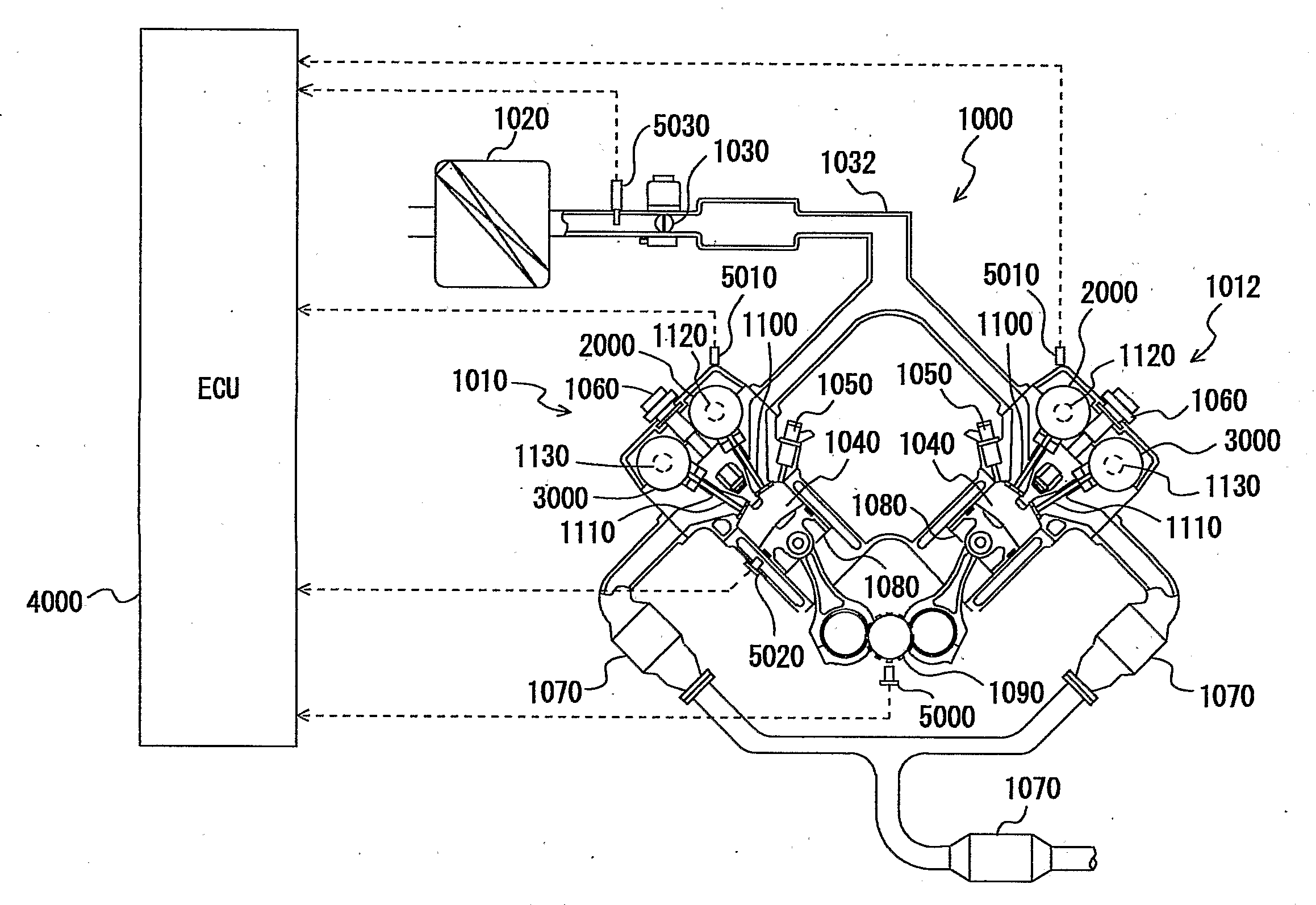
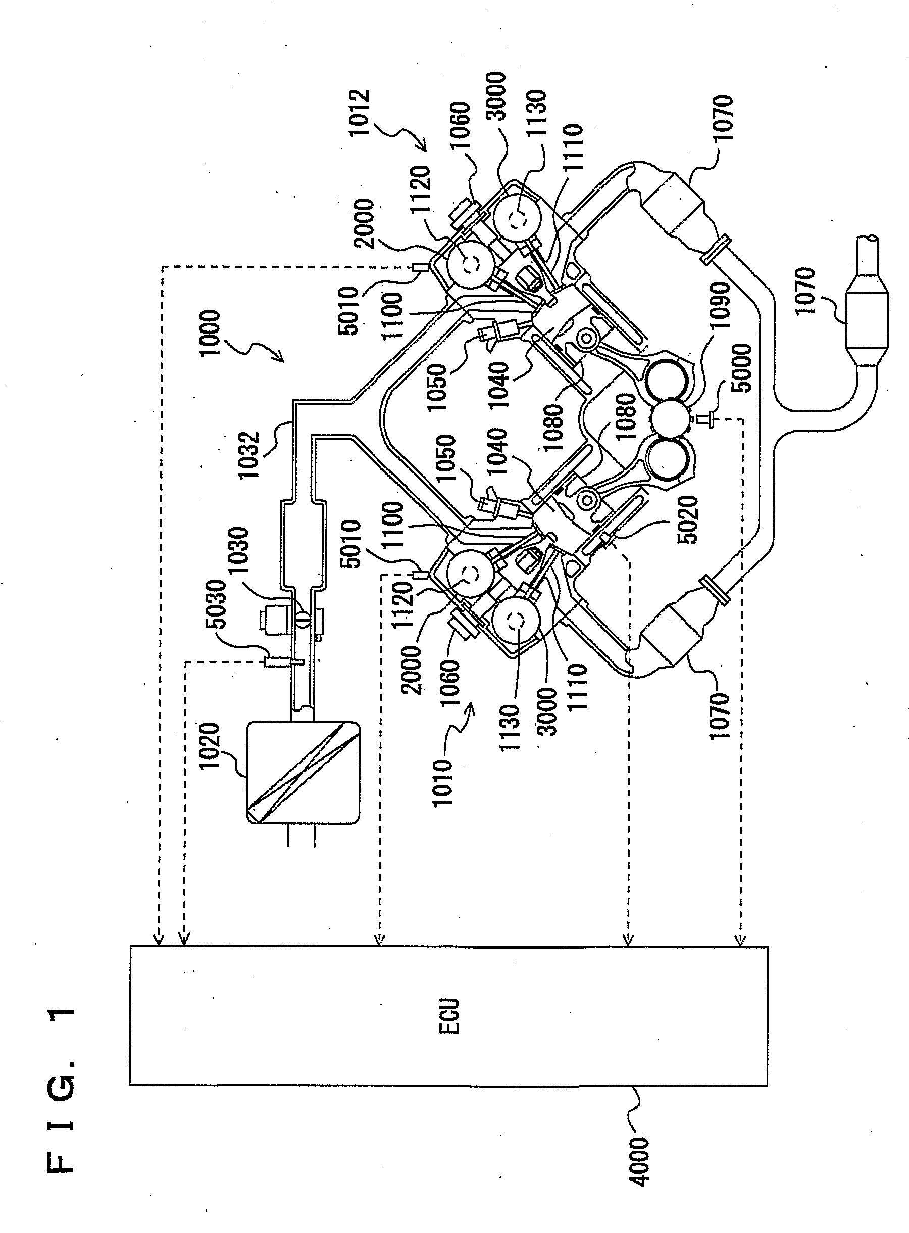
[0052]Referring to FIG. 1, a description is given of an engine of a vehicle on which a variable valve timing apparatus is mounted, according to an embodiment of the present invention.

[0053]An engine 1000 is a V-type 8-cylinder engine having a first bank 1010 and a second bank 1012 each including a group of four cylinders. Here, application of the present invention is not limited to any engine type, and the variable valve timing apparatus that will be described in the following is applicable to an engine of the type different from the V-type 8 cylinder engine.

[0054]Into engine 1000, air is sucked from an air cleaner 1020. The quantity of sucked air is adjusted by a throttle valve 1030. Thr...


PUM


Abstract

When the engine speed is high (determination of YES at S100), actual intake valve phase is calculated based on rotation phase difference between rotation angles of crankshaft and camshaft, detected by using a crank angle signal and a cam angle signal, and actual valve timing is detected therefrom. When the engine speed is low (determination of NO at S100) and the crank angle signal and cam angle signal are unstable, an amount of change in camshaft rotation phase by the VVT mechanism in accordance with the operation amount of actuator detected by a motor rotation angle signal is calculated successively, and based on an accumulation of the amount of change, the actual intake valve phase is calculated, and the actual valve timing is detected.

Description

TECHNICAL FIELD[0001]The present invention relates to a variable valve timing apparatus. In particular, the invention relates to a variable valve timing apparatus having a motor as an actuator (having a mechanism that changes the timing at which a valve is opened / closed by an amount of change according to an operation amount of an actuator).BACKGROUND ART[0002]A VVT (Variable Valve Timing) apparatus has conventionally been known that changes the phase (crank angle) in (at) which an intake valve or an exhaust valve is opened / closed, according to an operating condition. Generally, in the variable valve timing apparatus, the phase is changed by rotating a camshaft, which opens / closes the intake valve or exhaust valve, relative to a sprocket or the like. The camshaft is rotated by an actuator such as a hydraulic or electric motor.[0003]For accurate control of the valve timing using such a variable valve timing, it is necessary to detect the actual valve timing (that is, camshaft phase) ...

Claims


Application Information

Patent Timeline
Patent Type & Authority Applications(United States)
IPC IPC(8): F02D13/00F01L1/34
CPCF01L1/352F01L2001/0537F01L2800/00F01L2800/12F01L2820/032Y02T10/18F01L2820/042F02D13/0219F02D41/009F02D2041/001F01L2820/041Y02T10/12F01L1/34F02D13/02
Inventor MASHIKI, ZENICHIROINOUE, YASUMICHITAKAGI, NOBORUMORIYA, YOSHIHITOURUSHIHATA, HARUYUKI
Owner TOYOTA JIDOSHA KK
Features
  • Generate Ideas
  • Intellectual Property
  • Life Sciences
  • Materials
  • Tech Scout
  • Unparalleled Data Quality
  • Higher Quality Content
  • 60% Fewer Hallucinations
Learn More