Blood pressure pulse wave measurement apparatus
a pulse wave measurement and pulse wave technology, applied in the field of blood pressure pulse wave measurement apparatus, can solve the problems of requiring a large amount of labor and time, and achieve the effect of easy chang
- Summary
- Abstract
- Description
- Claims
- Application Information
AI Technical Summary
Benefits of technology
Problems solved by technology
Method used
Image

Examples
embodiment
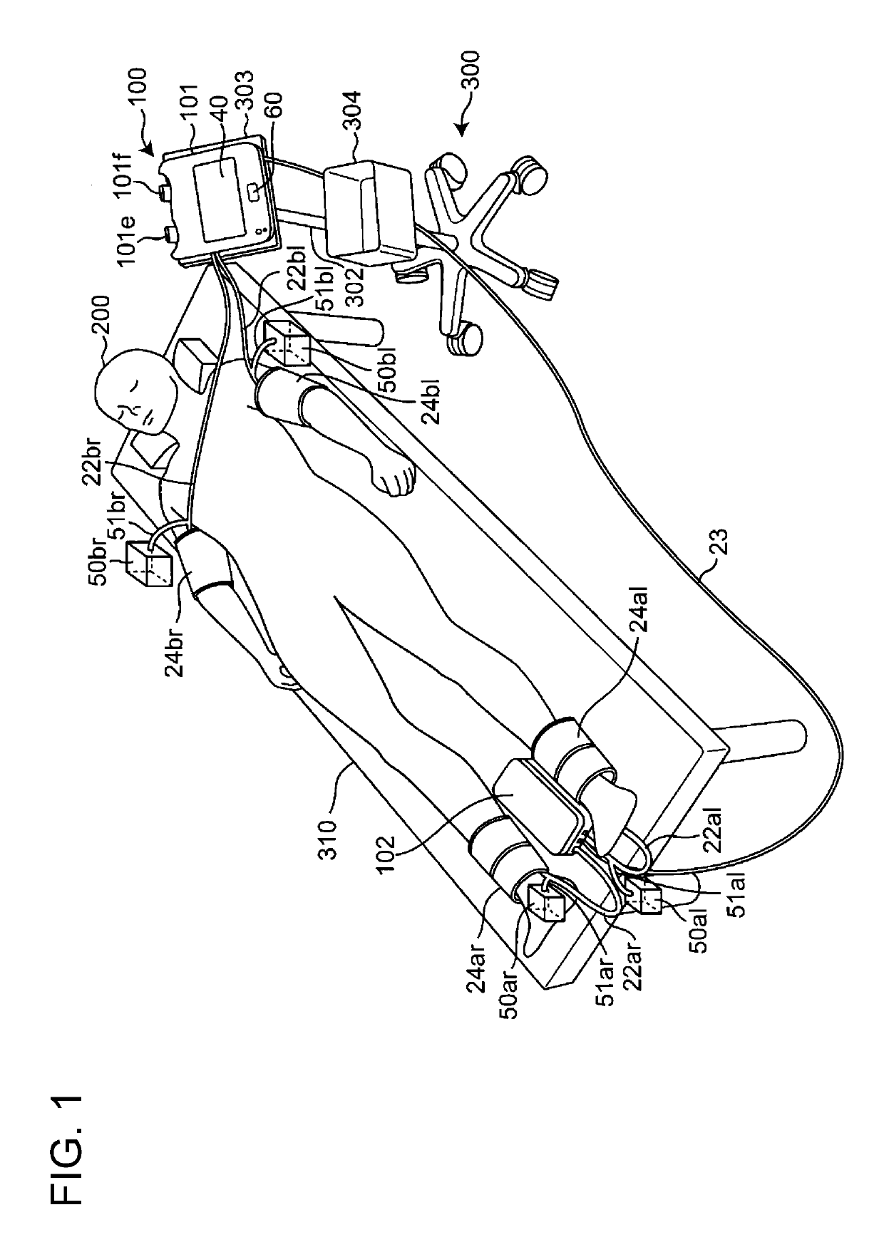
[0042]FIG. 1 is a perspective view showing a state in which a blood pressure pulse wave measurement apparatus of the present invention is used. The blood pressure pulse wave measurement apparatus 100 includes a main unit 101, which is a first housing, an ankle unit 102, which is a second housing, and four cuffs 24ar, 24al, 24br, and 24bl.
[0043]As shown in FIG. 1, a storage wagon 300 includes legs 301 with casters, a support column 302 provided in a standing manner on the legs 301, a placement platform 303 attached to the leading end of the support column 302, and a storage box 304 that is attached to the support column 302 and has an opening facing upward. The main unit 101 is placed on the placement platform 303. The ankle unit 102, right ankle (right lower limb) and left ankle (left lower limb) cuffs 24ar and 24al serving as second cuffs are stored in the storage box 304. The right upper arm (right upper limb) and left upper arm (left upper limb) cuffs 24br and 24bl serving as fi...
working examples
Working Example 1
[0075]First, changes in the fluid transfer characteristic of the tube 22br when the length of the tube 22br is 1.1 meters, which is contracted compared to 2 meters, which is the first reference length, will be described below.
[0076]FIG. 4A is a graph relating to the fluid transfer characteristic, indicating the change in the gain with respect to the frequency of the tube 22br shown in FIG. 1, when the capacity of the air tank 50br shown in FIG. 1 is set to 0 cc, and FIG. 4B is a graph relating to the fluid transfer characteristic, indicating the change in the phase with respect to the frequency of the tube 22br shown in FIG. 1, when the capacity of the air tank 50br shown in FIG. 1 is set to 0 cc. In FIGS. 4A and 4B, the fluid transfer characteristic of the tube 22br when the length of the tube 22br is set to 2 meters (reference length) is indicated by a solid line, and the fluid transfer characteristic of the tube 22br when the length of the tube 22br is set to 1.1...
modified example
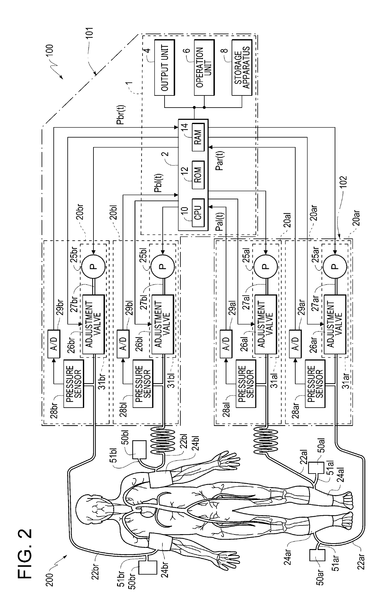
[0085]FIG. 7 is a block diagram schematically showing a configuration of a control system inside of a blood pressure pulse wave measurement apparatus 100A of the present invention. The blood pressure pulse wave measurement apparatus 100A according to the present modified example differs from the blood pressure pulse wave measurement apparatus 100 shown in FIG. 2 in that it includes air tanks 50Abr and 50Abl provided on the end portions of the tubes 22br and 22bl in the main unit 101, and air tanks 50Aar and 50Aal included on the end portions of the tubes 22ar and 22al in the ankle unit 102, instead of the air tanks 50ar, 50al, 50br, and 50bl and the tubes 51ar, 51al, 51br, and 51bl.
[0086]With the blood pressure pulse wave measurement apparatus 100A according to the modified example above, operations and effects similar to those of the above-described embodiment can be obtained. Furthermore, compared to the above-described embodiment, the air tanks are provided inside of the main un...
PUM
 Abstract
Description
Claims
Application Information
 - R&D Engineer
- R&D Manager
- IP Professional
- Industry Leading Data Capabilities
- Powerful AI technology
- Patent DNA Extraction
Browse by: Latest US Patents, China's latest patents, Technical Efficacy Thesaurus, Application Domain, Technology Topic.
© 2024 PatSnap. All rights reserved.Legal|Privacy policy|Modern Slavery Act Transparency Statement|Sitemap