Positioning unit and contacting method

a technology of positioning unit and contacting method, which is applied in the direction of electric vehicle charging technology, vehicle components, climate sustainability, etc., can solve the problems of no adjustment force at all or only very little on the articulating arm device, and the charging contact cannot be moved and charged, so as to prevent overloading of the electric motor and constant contact force

Active Publication Date: 2019-04-11
SCHUNK TRANSIT SYST GMBH
View PDF26 Cites 6 Cited by
  • Summary
  • Abstract
  • Description
  • Claims
  • Application Information

AI Technical Summary

Benefits of technology

[0019]The contact force can be formed independent from a relative distance of the charging contact surface or of the contact position to the retracted position of the positioning unit. Therefore, it is possible to also contact vehicles that have different heights relative to a road with the positioning unit.
[0020]In the contact position, during adjustment of a relative distance of the charging contact surface or of the contact position from the retracted position of the positioning unit, the contact force can be constant. A change of a relative distance of a vehicle to the road always results in a change of the relative distance between the contact position and the retracted position as well. A change of the relative distance can be caused by the vehicle being lowered via a running gear or by the vehicle being loaded. Since the contact force is comparatively large relative to the adjustment force, the contact force can be substantially constant, even if the relative distance is changed. A constant contact force can be formed even more easily independent from the relative distance if the contact force is controlled by the control device in accordance with the torque of the electric motor. If the relative distance is increased by lowering the vehicle, the contact force and thus directly a torque of the electric motor decrease, the torque then being increased again by the control device, resulting in a constant contact force. Vice versa, decreasing the relative distance leads to an increase of a contact force and thus of the torque, which the control device can counteract by decreasing the torque.
[0021]The torque of the electric motor can be set in accordance with a position of the articulated arm device or the adjustment drive by means of the control device. Thereby it is then possible for a direct force action on the articulated arm device and, if applicable, on the contact element to be ideally matched to the respective position of the articulated arm device and therefore also for the direct force acting on the charging contact surface to be substantially constant irrespective of the position of the articulated arm device. A position of the articulated arm device can be detected through, for example, a displacement sensor and the torque can be adjusted beforehand in accordance with the position by the control device, so that controlling the torque for the adjustment of the contact force will not require any large torque steps.
[0022]When a limit value of the torque is exceeded, the control device can also detect that the contact position has been reached. The charging contact encounters the charging contact surface in the contact position, which causes the torque of the electric motor to increase significantly. This increase of the torque can be detected as the arrival of the control device in the contact position. For example, a possibly existing speed control of the electric motor can then be turned off because it is only necessary to readjust the torque of the electric motor in the contact position. Also, an enable signal for the transfer of energy from a charging station can then be released in the contact position by means of the control device, for example. Further sensors for the detection of the contact position are therefore not necessary.
[0023]The torque of the electric motor can be limited and constantly maintained by means of the control device once a target value of the torque has been reached. By limiting the torque, overloading of the electric motor is prevented as a start. Furthermore, it is then also possible to make the contact force constant. The same applies to an extension and a retracting speed of the charging contact, which can then be increased within limits.
[0024]The target value of the torque can be controlled within a tolerance range of + / −10% by means of the control device. This tolerance range is completely sufficient for forming a substantially constant contact force, so that a particularly precise detection of the torque of the electric motor through the control device is unnecessary. The control device can therefore be designed in a more inexpensive manner.

Problems solved by technology

In the retracted position, however, no adjustment force at all or only very little can act on the articulated arm device, so that no movement of the articulated arm device and of the charging contact is possible.

Method used


Image

  • Positioning unit and contacting method
  • Positioning unit and contacting method
  • Positioning unit and contacting method

Examples


first embodiment

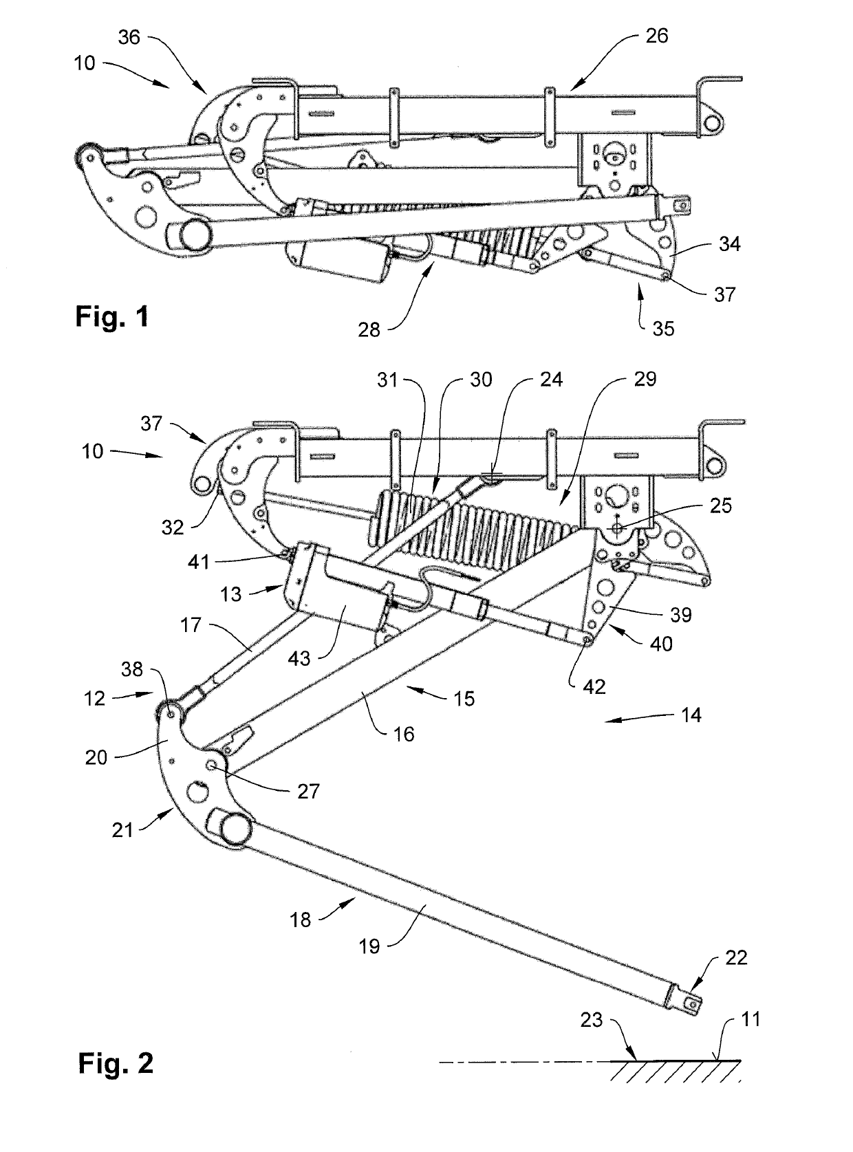
[0036]An overview of FIGS. 1 and 2 shows a positioning unit 10 in various positions. A contacting of a charging contact surface 11 is only illustrated symbolically. The positioning unit 10 comprises an articulated arm device 12 and an adjustment drive 13 for driving the articulated arm device 12. The articulated arm device 12 is designed as a single-arm system 14 and comprises an upper scissor 15 with an upper scissors arm 16 and an upper coupling rod 17 as well as a lower scissor 18 with a lower scissors arm 19 and a lower coupling rod 20. An upper coupling link 21 is swivel-mounted to the upper scissors arm 16, so that a mount 22 of the positioning unit 10 for an electrical charging contact (not shown) of the positioning unit 10 can always be moved parallel to a horizontal plane 23. For this purpose, the upper coupling link 21 is connected to the upper coupling rod 17 via an axis 38. The lower scissors arm 19 and the lower coupling rod 20 are swivel-mounted to fixed bearings 24 an...

second embodiment

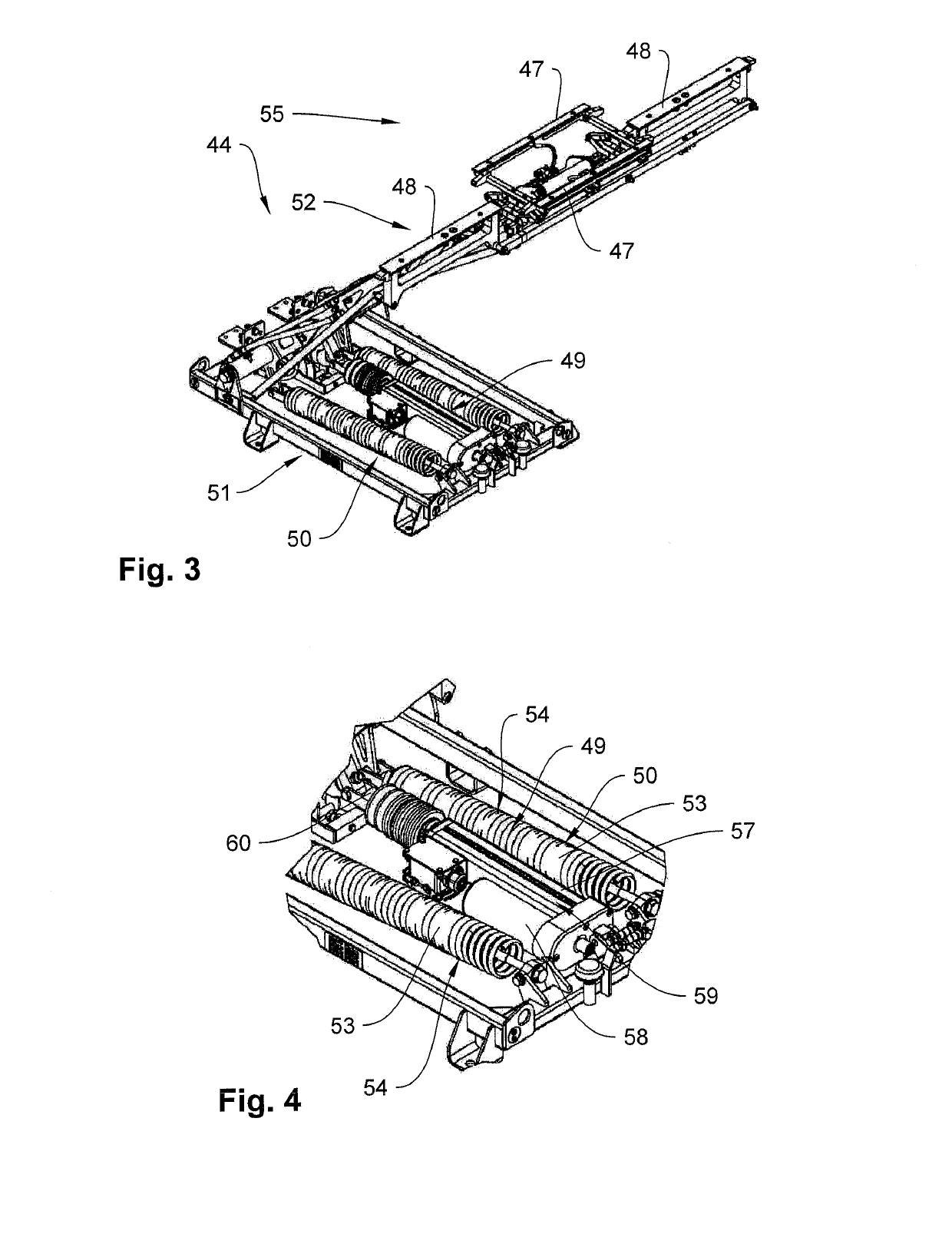
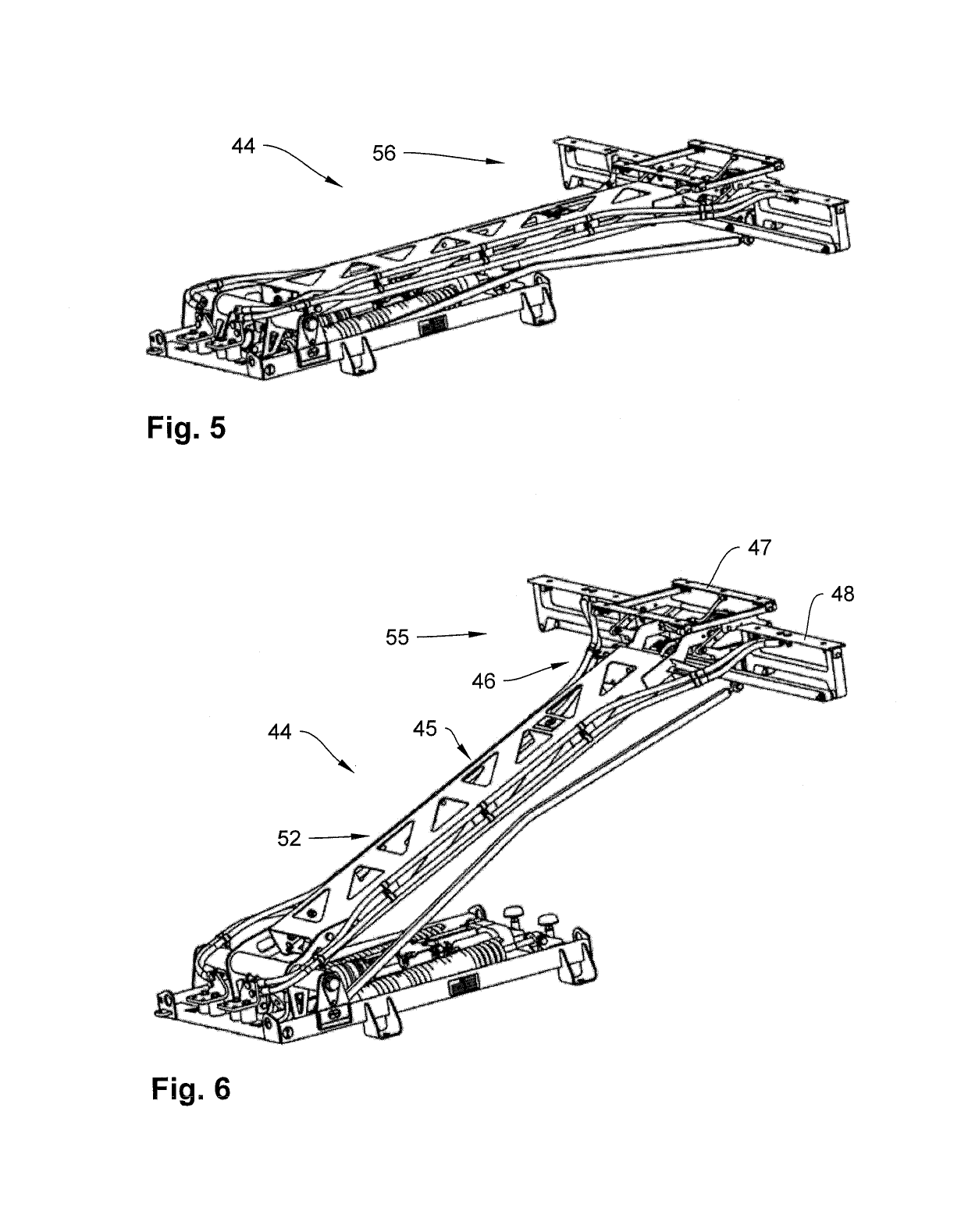
[0039]An overview of FIGS. 3 to 6 shows a positioning unit 44 that is mounted on the roof of an electrically driven vehicle (not shown). The positioning unit 44 substantially comprises an articulated arm device 45, at the end 46 of which charging contacts 47 and 48 are located for the contacting of a charging contact surface (not shown) above the vehicle. Furthermore, the positioning unit 44 comprises an adjustment drive 49 and a spring device 50 as well as a holding frame 51. The articulated arm device 45 is formed as a single-arm system 52 similar to the previously described single-arm system. The spring device 50 comprises two tension springs 53 that are formed as lifting springs 54 and exert a lifting force on the articulated arm device 45. Here, the lifting force is determined in a way that a gravitational force of the articulated arm device 45 together with the charging contacts 47 and 48 is greater than the lifting force, so that in the event of a power outage, for example, t...


PUM


Abstract

A positioning unit and method for forming an electrically conductive connection between a stationary charging station and a vehicle, wherein an electrical charging contact of a positioning unit is movable relative to a charging contact surface and contacted by the positioning unit having an articulated arm device and a corresponding drive device, wherein the charging contact includes a contact position for power transmission and a retracted position for power interruption, the drive device having an adjustment drive acting on the articulated arm device and a spring device wherein a contact force acting on the charging contact surface can be formed by the adjustment drive having a control device and an electric motor actuated by the control device, wherein the adjustment drive is designed such that a torque of the electric motor is detected by the control device, and the contact force controlled by the control device based on the torque.

Description

FIELD OF THE INVENTION[0001]This invention relates to a positioning unit as well as a method for forming an electrically conductive connection between a stationary charging station and a vehicle, in particular an electric bus or similar, wherein an electrical charging contact of the positioning unit can be moved relative to a charging contact surface and contacted with same by means of the positioning unit, wherein the positioning unit has an articulated arm device and a drive device for driving the articulated arm device, wherein the charging contact can be positioned between a contact position for power transmission and a retracted position for power interruption by means of the articulated arm device, wherein the drive device has an adjustment drive for forming an adjustment force acting on the articulated arm device and a spring device mechanically cooperating with the adjustment drive, wherein a contact force acting on the charging contact surface can be formed by the adjustmen...

Claims


Application Information

Patent Timeline
Patent Type & Authority Applications(United States)
IPC IPC(8): B60L5/30B60L5/24
CPCB60L5/30B60L5/24Y02T90/16B60L5/19
Inventor PACHLER, ALEXANDER
Owner SCHUNK TRANSIT SYST GMBH
Why Eureka
Try Eureka