Tensioner

a technology of tensioner and housing, which is applied in the direction of mechanical equipment, belts/chains/gearings, and mechanical components, can solve the problems of high design requirements, high oil supply pressure generation, and high design requirements, and achieve the effect of improving the efficiency of recirculation of oil in the tensioner, and reducing the risk of slipping

Active Publication Date: 2019-04-11
TSUBAKIMOTO CHAIN CO
View PDF0 Cites 7 Cited by
  • Summary
  • Abstract
  • Description
  • Claims
  • Application Information

AI Technical Summary

Benefits of technology

[0014]By designing the flow resistance of the housing oil supply hole to be high, therefore, the majority of the oil that leaks out of the pressure oil chamber between the outer peripheral surface of the plunger and the inner peripheral surface of the plunger housing hole when the oil pressure in the pressure oil chamber increases can be returned to the oil storage chamber through the communication adjustment groove and the plunger oil supply hole. As a result, the efficiency of recirculation of oil in the tensioner can be improved, and the oil supply pressure of the oil pump or the like can be designed to be low.
[0015]Accordingly, reductions in oil consumption and the power of an oil pressure generation source such as the oil pump can be achieved, and dependency on the oil supplied from the oil pump or the like can also be reduced. As a result, effects of the type, temperature, amount, and so on of the oil supplied from the oil pump or the like can be reduced, and a chain holding force can be stabilized.
[0016]Furthermore, in the case of a so-called auto tensioner, in which oil is completed sealed within the tensioner, a high-precision sealing mechanism must be provided to ensure that the oil does not leak out to the outside, but according to the present invention, the oil can be replenished from the outside of the tensioner, and therefore a high-precision sealing mechanism is not required, enabling a reduction in cost.

Problems solved by technology

As a result, a problem occurs in that an oil supply pressure generated by the oil pump or the like must be designed to be high.
Further, the need to supply oil using an oil pump or the like may be eliminated by completely sealing the oil in the tensioner, as in a so-called auto-tensioner, but in an auto-tensioner, a problem exists in that a high-precision sealing mechanism must be provided to ensure that the oil does not leak out to the outside.

Method used


Image

  • Tensioner
  • Tensioner
  • Tensioner

Examples


Embodiment Construction

[0025]A tensioner 10 according to an embodiment of the present invention will be described below on the basis of the figures.

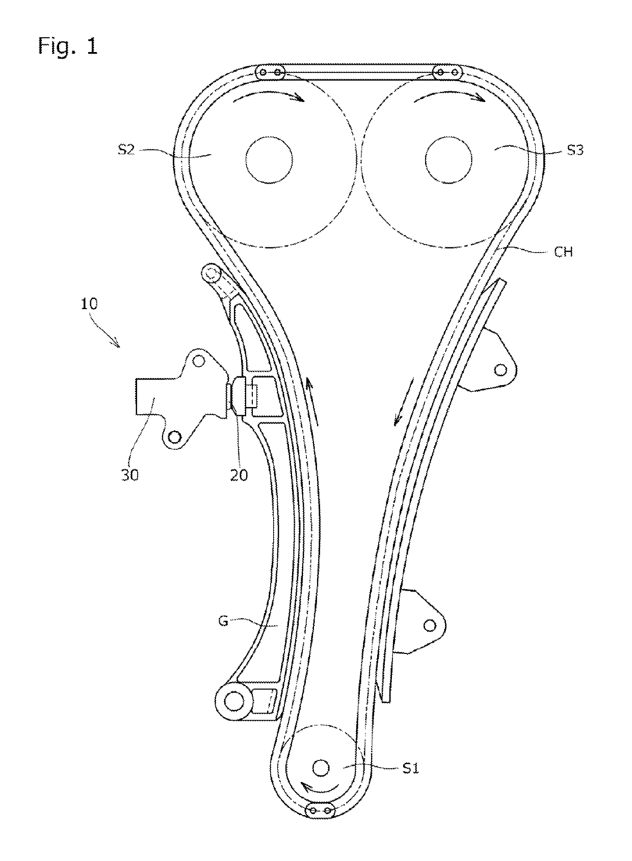
[0026]First, as shown in FIG. 1, the tensioner 10 according to this embodiment is incorporated into a chain transmission device used in a timing system of an automobile engine or the like, and is attached to an engine block (not shown) in order to apply appropriate tension, via a tensioner lever G, to a slack side of a transmission chain CH wound around a plurality of sprockets S1 to S3, thereby suppressing vibration of the transmission chain CH during travel.

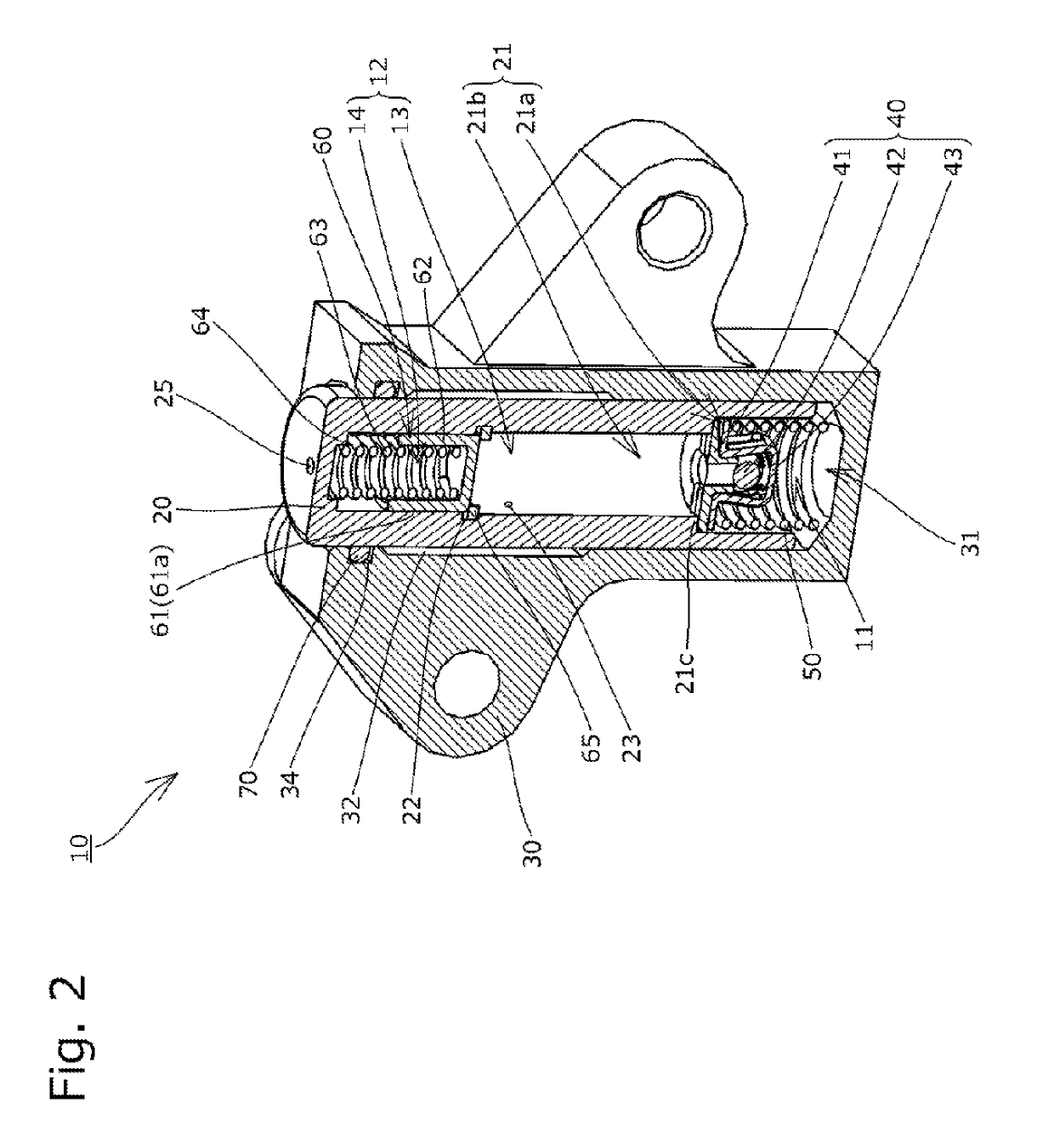
[0027]As shown in FIG. 2, the tensioner 10 includes a plunger 20 having a cylindrical plunger hole 21 that is open on a rear side, a housing 30 having a plunger housing hole 31 in which the plunger 20 is housed, a check valve 40 that divides a space between the housing 30 and the plunger 20 into a front side interior space 12 and a rear side pressure oil chamber 11 and allows oil to flow into the pressure...


PUM


Abstract

Provided is a tensioner with which efficiency of recirculation of oil can be improved and dependency on oil supplied from an oil pump or the like can be reduced. The tensioner includes a pressure adjustment mechanism, wherein the pressure adjustment mechanism includes a cylinder portion and a piston that is disposed in the cylinder portion so as to be capable of moving in a front-rear direction and that divides an interior space into an oil storage chamber and an adjustment space, and a liquid-tight state is maintained between the cylinder portion and the piston in all positions between a position of the piston where the piston has moved closest to the oil storage chamber side and a position of the piston where the piston has moved closest to the adjustment space side.

Description

BACKGROUND OF THE INVENTION1. Field of the Invention[0001]The present invention relates to a tensioner used to apply appropriate tension to a transmission belt or a transmission chain in a timing system of an engine or the like.2. Description of the Related Art[0002]A tensioner for maintaining a chain or the like at an appropriate tension is commonly used conventionally. For example, in a chain guide mechanism in which a tensioner lever guides a sliding motion of a transmission chain such as a roller chain that is wound endlessly around sprockets provided respectively on a crankshaft and a cam shaft in an engine room, for example, using a tensioner to bias the tensioner lever so that the tension remains appropriate is well-known technology.[0003]A conventional tensioner 510 used in a chain guide mechanism of this type, as illustrated schematically in FIG. 7, for example, includes a housing 530 having a cylindrical plunger housing hole 531 that is open at one end, a cylindrical plung...

Claims


Application Information

Patent Timeline
Patent Type & Authority Applications(United States)
IPC IPC(8): F16H7/08
CPCF16H7/0848F16H2007/0812F16H2007/0859F16H2007/0806F16H7/08
Inventor YOSHIDA, OSAMUWATANABE, MASANORITAKAGI, YUDAIKUREMATSU, YUJI
Owner TSUBAKIMOTO CHAIN CO
Why Eureka
Try Eureka