
Method and devices for controlling a fluid transportation network

a fluid transportation network and fluid technology, applied in space heating and ventilation, lighting and heating apparatus, heating types, etc., can solve the problems of particularly high complexity of installation process, and achieve the effects of reducing hardware overhead, increasing energy efficiency in fluid transportation, and reducing energy consumption

Active Publication Date: 2019-04-11
BELIMO HOLDING AG
View PDF27 Cites 2 Cited by
  • Summary
  • Abstract
  • Description
  • Claims
  • Application Information

AI Technical Summary

Benefits of technology

The patent is about a system for regulating fluid flow in a network. The system uses pressure regulators and valves to control the flow of fluid through the network. The system also includes a processing unit that receives information about the valves and determines the best position for them to regulate pressure and flow. This system can be used in dually heated or cooled networks using separate supply lines, allowing for more efficient energy usage and control of pumping power. The technical effects of this patent text are reduced hardware requirements and increased energy efficiency in fluid transportation networks.

Problems solved by technology

The compensation method requires multiple pressure connection points for each compensating organ, and is not designed for a dynamic balancing of a fluid transport system.
As a result, a great degree of complexity is particularly inherent in the installation process.

Method used


Image

  • Method and devices for controlling a fluid transportation network
  • Method and devices for controlling a fluid transportation network
  • Method and devices for controlling a fluid transportation network

Examples


Embodiment Construction

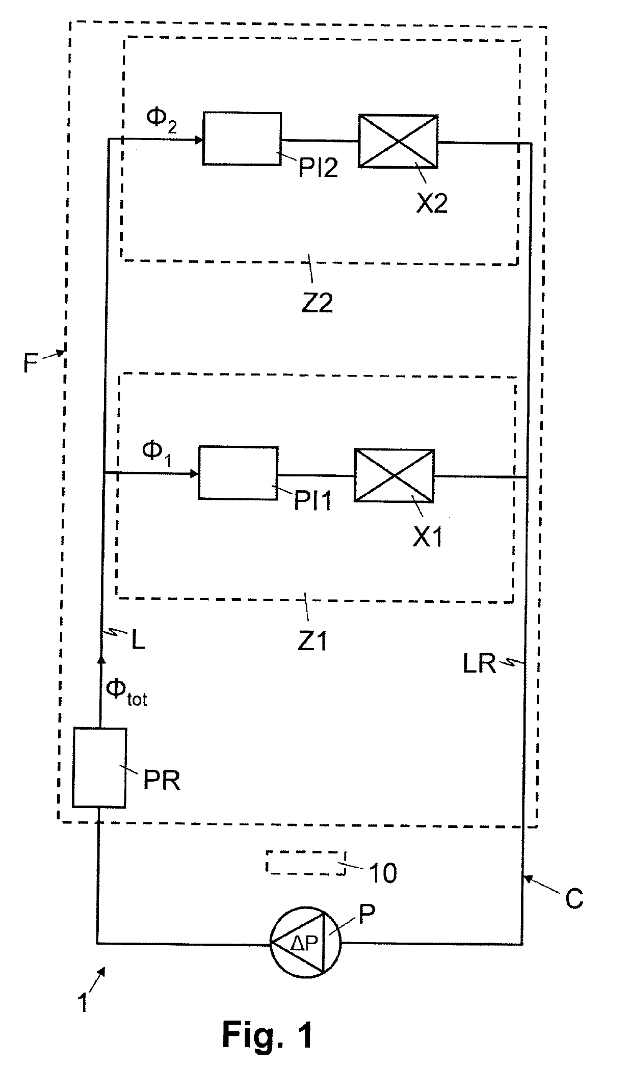
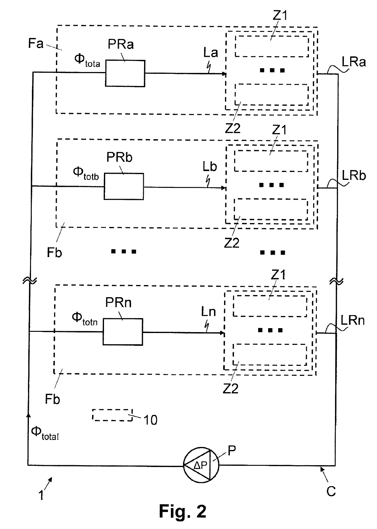
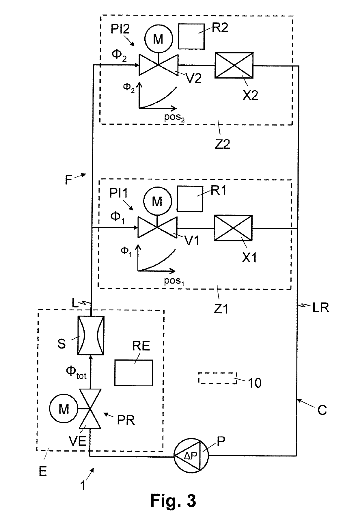
[0056]In FIGS. 1 to 5, reference numeral 1 refers to a fluid transportation network, e.g. a hydraulic or hydronic network, which comprises a plurality of parallel zones Z1, Z2. The fluid transportation network 1 includes one or more fluid transportation circuits C, C1, C2 with fluid transportation lines, e.g. pipes, for transporting a liquid heat transportation medium, e.g. water. As illustrated schematically in FIGS. 1, 3 and 5, each of the zones Z1, Z2 comprises one or more thermal energy exchangers X1, X2, e.g. a heat exchanger for heating the zone Z1, Z2 or a cooling device for cooling the zone Z1, Z2. As indicated in FIGS. 1 and 3, for implementing the zones Z1, Z2 as pressure independent branches, the zones Z1, Z2 further comprise a pressure invariant regulating system PI1, PI2. The pressure invariant regulating systems PI1, PI2 are each implemented as a regulating zone valve V1, V2, V61, V62 for regulating the flow of fluid ϕ1, ϕ2 through the respective zone Z1, Z2 or thermal...


PUM


Abstract

A fluid transportation network (1) comprises a plurality of parallel zones (Z1, Z2), fed by a common supply line (L), with a regulating zone valve (V1, V2) in each zone (Z1, Z2) for regulating a flow of fluid (ϕ1, ϕ2) through the respective zone (Z1, Z2). A processing unit (RE) receives valve positions (pos1, pos2) of the regulating zone valves (V1, V2) and determines and sets an adjusted valve position for a line valve (VE) arranged in the supply line (L), depending on the valve positions (pos1, pos2) of the regulating zone valves (V1, V2). A processing unit (RE) further receives a measurement of a total flow of fluid (ϕtot) through the supply line (L) and determines and sets adjusted valve positions for the regulating zone valves (V1, V2), depending on the measurement of the total flow of fluid (ϕtot) through the supply line (L).

Description

FIELD OF THE INVENTION[0001]The present invention relates to a method and devices for controlling a fluid transportation network. Specifically, the present invention relates to a fluid transportation network and to a method and devices for controlling the fluid transportation network, which comprises one or more network sections, whereby each network section is connected to a fluid transportation circuit through a respective supply line and comprises one or more parallel zones.BACKGROUND OF THE INVENTION[0002]Fluid transport systems typically comprise multiple consumers, meaning parallel branches or lines, through which a liquid or gaseous fluid is transported—for example to distribute thermal energy. The consumers typically have different designs, meaning that they have different diameters and / or lengths of the transport lines—for example, pipe conduits—and have different and / or varying flow volumes and / or throughput. In order to undertake a balanced and / or compensated distribution...

Claims


Application Information

Patent Timeline
Patent Type & Authority Applications(United States)
IPC IPC(8): F24D10/00F24D19/10
CPCF24D2220/0207F24D2220/0228F24D2220/06F24D2220/0292F24D19/1015F24D2220/046F24D2220/048F24D2220/0242F24D10/003F24D2220/044Y02B30/17
Inventor MISCHLER, STEFANAEBERHARD, RONALDREIDER, FORESTTHUILLARD, MARC
Owner BELIMO HOLDING AG
Learn More