
Interleaved trellis coded modulation and decoding

Inactive Publication Date: 2005-01-27
PARHI KESHAB K +1
View PDF11 Cites 5 Cited by
  • Summary
  • Abstract
  • Description
  • Claims
  • Application Information

AI Technical Summary

Benefits of technology

[0005] The present invention provides a new way to use trellis coded modulation for high speed communication systems with multiple parallel channels. A typical example of such systems is 1000BASE-T, where data communication is performed simultaneously over four pairs of copper cables. Consider a communication system of higher throughput which uses 4 dimensional trellis coded modulation over four pairs of channels, traditional trellis coded modulation scheme as in 1000BASE-T leads to a design where the corresponding decoder with a long critical path needs to operate at higher speed than in 1000BASE-T. It is difficult to meet the critical path requirements of such a decoder. To solve the problem, two interleaved trellis coded modulation schemes are proposed. The inherent decoding speed requirements are relaxed by factors of 4 and 2, respectively. Parallel decoding of the interleaved codes requires multiple decoders. To reduce the hardware overhead, time-multiplexed or folded decoder structures are pro—posed where only one decoder is needed and each delay in the decoder is replaced with four delays for scheme I and two delays for scheme II, respectively. These delays can be used to reduce the critical path. Compared with the conventional decoder, the folded decoders for the two proposed schemes can achieve speedups of 4 and 2, respectively.

Problems solved by technology

It is difficult to meet the critical path requirements of such a decoder.

Method used


Image

  • Interleaved trellis coded modulation and decoding
  • Interleaved trellis coded modulation and decoding
  • Interleaved trellis coded modulation and decoding

Examples


Embodiment Construction

[0017] Background on Conventional Trellis Coded Modulation and Decoding

[0018] To explain the principles of the invention better, we assume there is a communication system which uses trellis coded modulation and four pair of wires, just like in 1000BASE-T. We further assume the trellis code is also a 4 dimensional trellis code. But the throughput of the system is 10 Gbps, and the symbol rate is 833 MHz with each 1D symbol representing 3 bits of information.

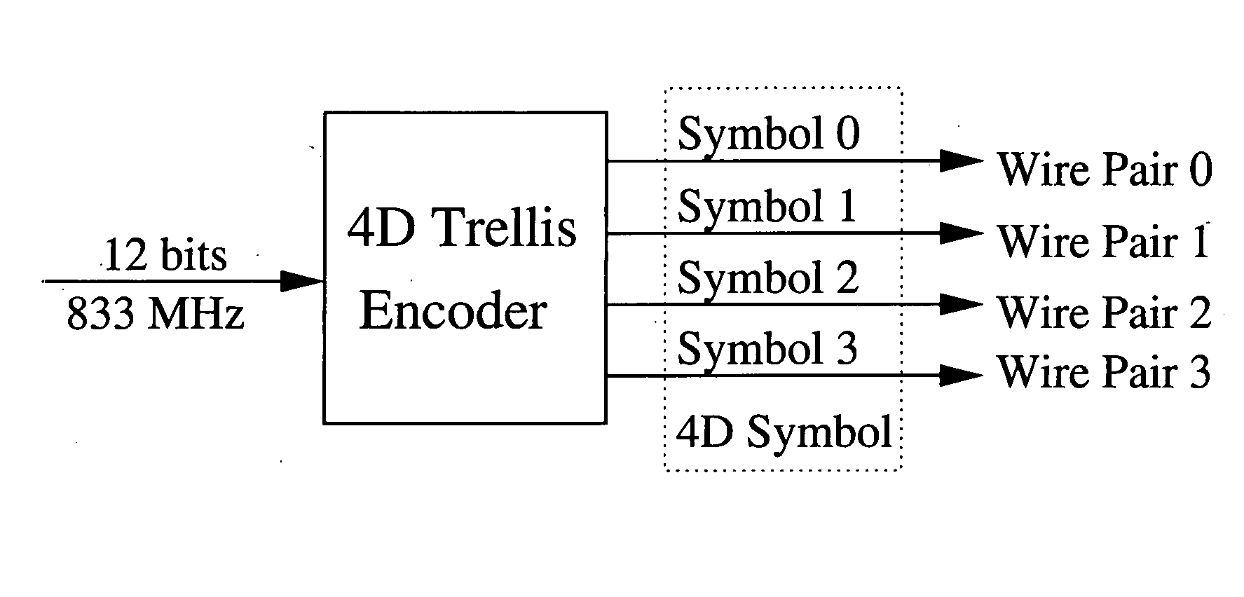
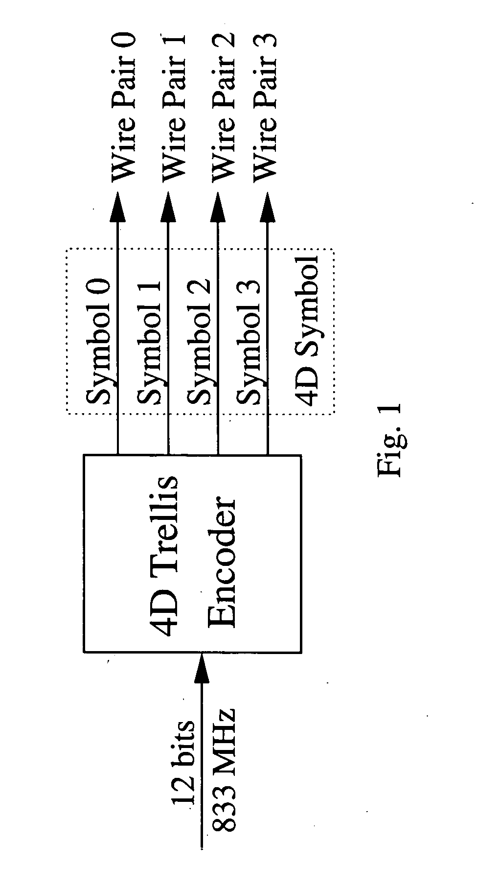
[0019] The trellis coded modulation can be used in a traditional way as in 1000BASE-T, where four wire pairs share a trellis encoder, as illustrated in FIG. 1. Each time, the encoder takes 12 bits of information and converts them to a 4D symbol at a speed of 833 MHz. Each 4D symbol contains 4 1D symbols. The four 1D symbols are transmitted over the four pairs with one dimension per pair.

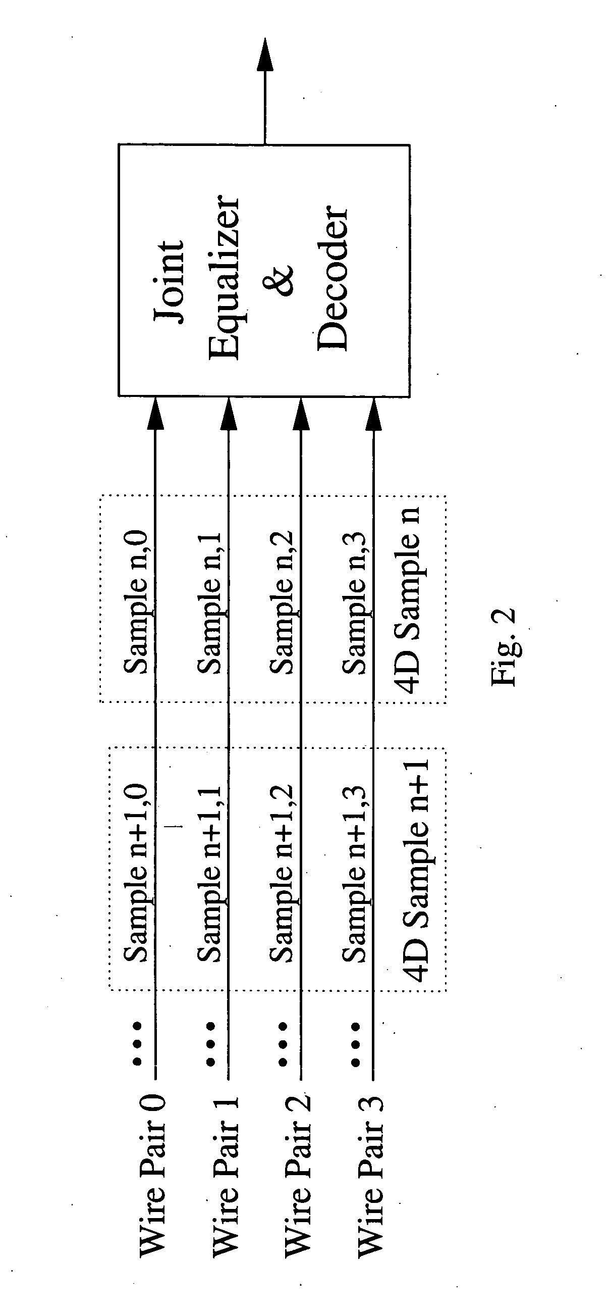
[0020]FIG. 2 shows the corresponding decoding scheme. To meet the throughput requirement, the joint equalizer and decoder (JED), which implement...


PUM


Abstract

Digital communications systems employ trellis coded modulation schemes. A K-dimensional trellis coded modulated symbol is transmitted over M channels in K / M cycles (where M divides K). K / M consecutive data units are transmitted serially in a time multiplexed manner in K / M consecutive cycles over one channel. If M=1, then each symbol is transmitted over one channel in K cycles in a time-multiplexed manner. At the receiver, a symbol is formed by grouping the data received from M channels in K / M cycles and this symbol is then decoded by a joint equalizer and decoder. If the number of parallel channels is N, then N / M trellis coded modulators and N / M decoders can be used in parallel. The advantage of this approach is an increase in speed by factor N / M. The N / M trellis coded modulation and joint equalization and decoding operations can also be implemented by using fewer hardware trellis coded modulators and decoders using folding technique where multiple operations are time-multiplexed to the same hardware modulator or decoder which are operated by higher clock speed.

Description

CROSS-REFERENCE TO RELATED APPLICATIONS [0001] This application claims the benefit of U.S. Provisional Application No. 60 / 488,874, filed on Jul. 21, 2004, which is incorporated herein by reference in its entirety.FIELD OF THE INVENTION [0002] The present invention relates to data transmission. More particularly, it relates to the way we use trellis coded modulation for data transmission. BACKGROUND OF THE INVENTION [0003] Trellis coded modulation has been widely used in many communication systems, such as 1000BASE-T (Gigabit Ethernet over copper), which uses a 4 dimensional (4D) 8-state trellis code combined with 5-level pulse amplitude modulation. Usually, these systems suffer inter-symbol interference. One approach to decode the trellis coded signals is called (MLSE) maximum likelihood sequence estimation. However, it requires the use of a Viterbi decoder with a large number of states, as a result of the combination of trellis coding with the inter-symbol interference channel. Ano...

Claims


Application Information

Patent Timeline
IPC IPC(8): H04L1/00H04L25/14
CPCH04L1/0045H04L25/14H04L1/0071H04L1/006
Inventor PARHI, KESHAB K.GU, YONGRU
Owner PARHI KESHAB K
Learn More