Vehicular power transmitting device

a transmission device and transmission device technology, applied in mechanical devices, gearing details, transportation and packaging, etc., can solve the problems of insufficient provision of the oil passage for bringing lubricant oil from the breather chamber back into the housing, and achieve the effect of reducing the deterioration of the sealing property of the oil seal and high efficiency

Inactive Publication Date: 2019-04-18
TOYOTA JIDOSHA KK
View PDF6 Cites 6 Cited by
  • Summary
  • Abstract
  • Description
  • Claims
  • Application Information

AI Technical Summary

Benefits of technology

[0005]The present invention was made in view of the background art described above. It is therefore an object of the present invention to provide a vehicular power transmitting device provided with a breather device having a breather plug and a breather chamber for preventing or reducing leakage of a lubricant oil from a housing of the vehicular power transmitting device by ejecting an air from the housing into an outside atmosphere outside the housing, through the breather plug, when the pressure of the air within the housing is raised, which vehicular power transmitting device permits more effective prevention or reduction of the leakage of the lubricant oil from the housing.
[0009]In the vehicular power transmitting device according to the first mode of the invention, the power transmitting shaft accommodated within the housing is rotated by the drive power source, and rotatably supported by the housing through the tapered roller bearing, and the breather chamber of the breather device including the breather plug provided on the housing is held in communication between the outside atmosphere and the inside space within the housing through the breather plug. The housing includes the oil passage for communication between the breather chamber and the small-diameter end side space which is partially defined by the small-diameter end face of the tapered roller of the tapered roller bearing. When the tapered roller bearing is rotated, there arises a difference between peripheral velocities of a large-diameter end portion and a small-diameter end portion of the tapered roller of the tapered roller bearing, due to a difference between outside diameters of the large-diameter and small-diameter end portions. This difference of the peripheral velocities generates a gradient of an air pressure such that the air pressure is lower in the small-diameter end side space than in a large-diameter end side space partially defined by a large-diameter end face of the tapered roller of the tapered roller bearing, so that a lubricant oil is sucked and discharged from the breather chamber back into the housing through the oil passage, whereby leakage of the lubricant oil from the breather chamber into the outside atmosphere can be effectively prevented or reduced.
[0010]In the vehicular power transmitting device according to the second mode of the invention wherein the housing is provided with the oil seal on the side of the small-diameter end of the tapered roller of the tapered roller bearing, the lubricant oil can be effectively supplied to the oil seal which is located at the position at which the oil seal would be otherwise difficult to be sufficiently lubricated. Accordingly, the oil seal can be lubricated with a high degree of efficiency, and deterioration of sealing property of the oil seal can be effectively reduced.

Problems solved by technology

During running of a vehicle at a high speed wherein the air within the housing is rapidly expanded, however, mere provision of the oil passage for returning the lubricant oil from the breather chamber back into the housing may be insufficient.

Method used


Image

  • Vehicular power transmitting device
  • Vehicular power transmitting device
  • Vehicular power transmitting device

Examples


first embodiment

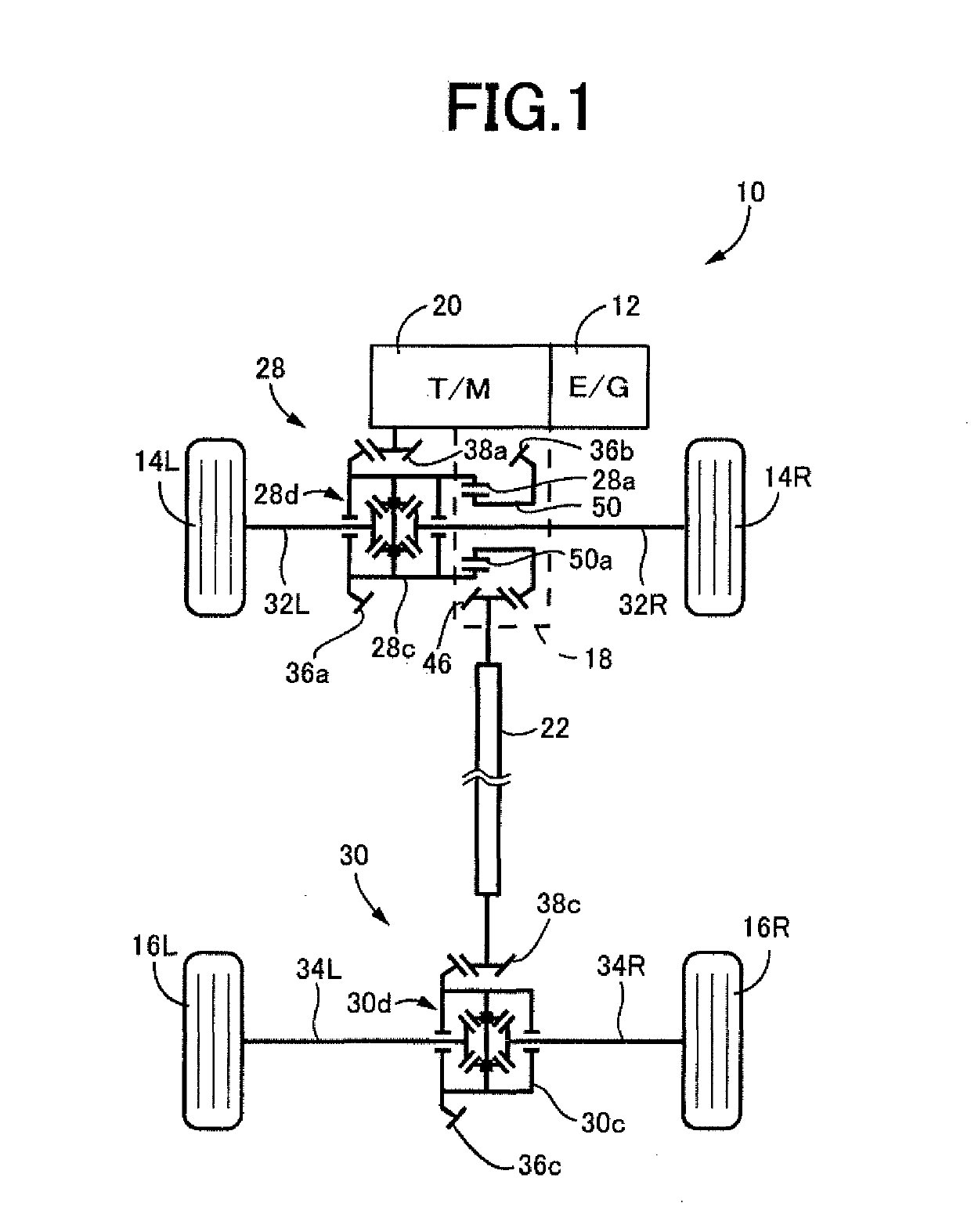
[0020]Reference is first made to FIG. 1, which is the schematic view showing an arrangement of a fourwheel-drive vehicle 10 constructed according to a first embodiment of this invention. As shown in FIG. 1, the four-wheel-drive vehicle 10 is of an FF (front-engine front-wheel drive) type having a power transmitting path through which a drive force of an engine 12 serving as a drive power source is transmitted to front wheels 14L and 14R (hereinafter referred to collectively as “front wheels 14” unless otherwise specified), and a power transmitting path through which the drive force of the engine 12 is transmitted to rear wheels 16L and 16R (hereinafter referred to collectively as “rear wheels 16” unless otherwise specified). The four-wheel-drive vehicle 10 includes an automatic transmission 20, a front wheel differential gear device 28, a transfer 18 serving as a power transmitting device, a propeller shaft 22, and a rear wheel differential gear device 30. It is noted that a fluid-o...

second embodiment

[0036]The cross sectional view of FIG. 8 shows the rear wheel differential gear device 30 taken in a horizontal plane including a third axis C3, which is an axis of rotation of the rear wheel axle 34, and the second axis C2, which is the axis of rotation of the drive pinion 38c connected to the propeller shaft 22. The rear wheel differential gear device 30 is accommodated within a housing 40c, and oil-tightly sealed with oil seals 70a and 70b, and other oil seals not shown in FIG. 8. The ring gear 36c meshing with the drive pinion 38c is fixed to a casing 30c with screws 74. The casing 30c which serves as a power transmitting shaft is supported by bearings 72a and 72b rotatably about the third axis C3 (axis of rotation of the rear wheel axle 34). A rotary motion of the casing 30c causes a rotary motion of a pinion shaft 66. The pinion shaft 66 is provided with a pinion gear 68 fixed thereto for rotation therewith, and the pinion gear 68 is held in meshing engagement with side gears ...


PUM


Abstract

A vehicular power transmitting device comprising: a power transmitting shaft rotated by a drive power source; a housing accommodating the power transmitting shaft and rotatably supporting the power transmitting shaft through a tapered roller bearing; and a breather device including a breather plug, and a breather chamber for communication between an outside atmosphere outside the housing and an inside space within the housing, through the breather plug, the vehicular power transmitting device being characterized in that: the housing includes an oil passage for communication between the breather chamber and a small-diameter end side space partially defined by a small-diameter end face of a tapered roller of the tapered roller bearing.

Description

[0001]This application claims priority from Japanese Patent Application No. 2017-198890 filed on Oct. 12, 2017, the disclosure of which is herein incorporated by reference in its entirety.FIELD OF THE INVENTION[0002]The present invention relates to a technique for preventing or reducing leakage of a lubricant oil through a breather device provided in communication with a housing accommodating a vehicular power transmitting device.BACKGROUND OF THE INVENTION[0003]The known vehicular power transmitting device is provided with a breather device having a breather plug and a breather chamber, so that an air within a housing of the vehicular power transmitting device is ejected into an outside atmosphere outside the housing, through the breather plug, to reduce a rise of the air pressure within the housing, for thereby preventing or reducing leakage of a lubricant oil from the housing. JP-2017-15156A discloses an example of such a vehicular power transmitting device including a differenti...

Claims


Application Information

Patent Timeline
Patent Type & Authority Applications(United States)
IPC IPC(8): F16H57/027F16H57/029F16H57/04
CPCF16H57/027F16H57/029F16H57/0483F16H57/0493F16H57/0409F16H57/0471F16H2057/02052B60K17/165B60K17/344F16C2361/61F16H57/0424F16H57/0472F16H2057/02043F16H57/0495
Inventor OMI, HIROSHIMINEZAWA, SHINGO
Owner TOYOTA JIDOSHA KK
Why Eureka
Try Eureka