
Rotor of rotating electrical machine

Inactive Publication Date: 2019-04-25
DENSO CORP
View PDF7 Cites 0 Cited by
  • Summary
  • Abstract
  • Description
  • Claims
  • Application Information

AI Technical Summary

Benefits of technology

The patent text discusses an invention related to a rotating electrical machine rotor. The technical effect of the invention is to improve the torque of the rotor by reducing the magnetic resistance and avoiding the lowering of strength due to vibration of claw-shaped magnetic pole portions. This is achieved by eliminating a clearance between the tubular member and the claw-shaped magnetic pole portions. The tubular member is made of multiple stacked steel plates and has a smaller inner diameter than the outer diameter of the claw-shaped magnetic pole portions, which ensures close contact between the tubular member and the claw-shaped magnetic pole portions. This results in no clearance between the tubular member and the claw-shaped magnetic pole portions, reducing magnetic resistance and avoiding vibration-induced performance issues.

Problems solved by technology

Specifically, in many cases, chattering noise of the claw-shaped magnetic pole portions due to vibration is taken as a factor for lowering of performance of a Lundell motor.
In this case, the stress concentration factor is increased at a distorted (plastically-deformed) portion, and therefore, this is obviously unfavorable in strength design.

Method used


Image

  • Rotor of rotating electrical machine
  • Rotor of rotating electrical machine
  • Rotor of rotating electrical machine

Examples


first embodiment

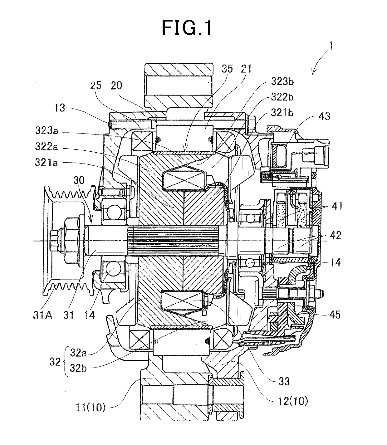
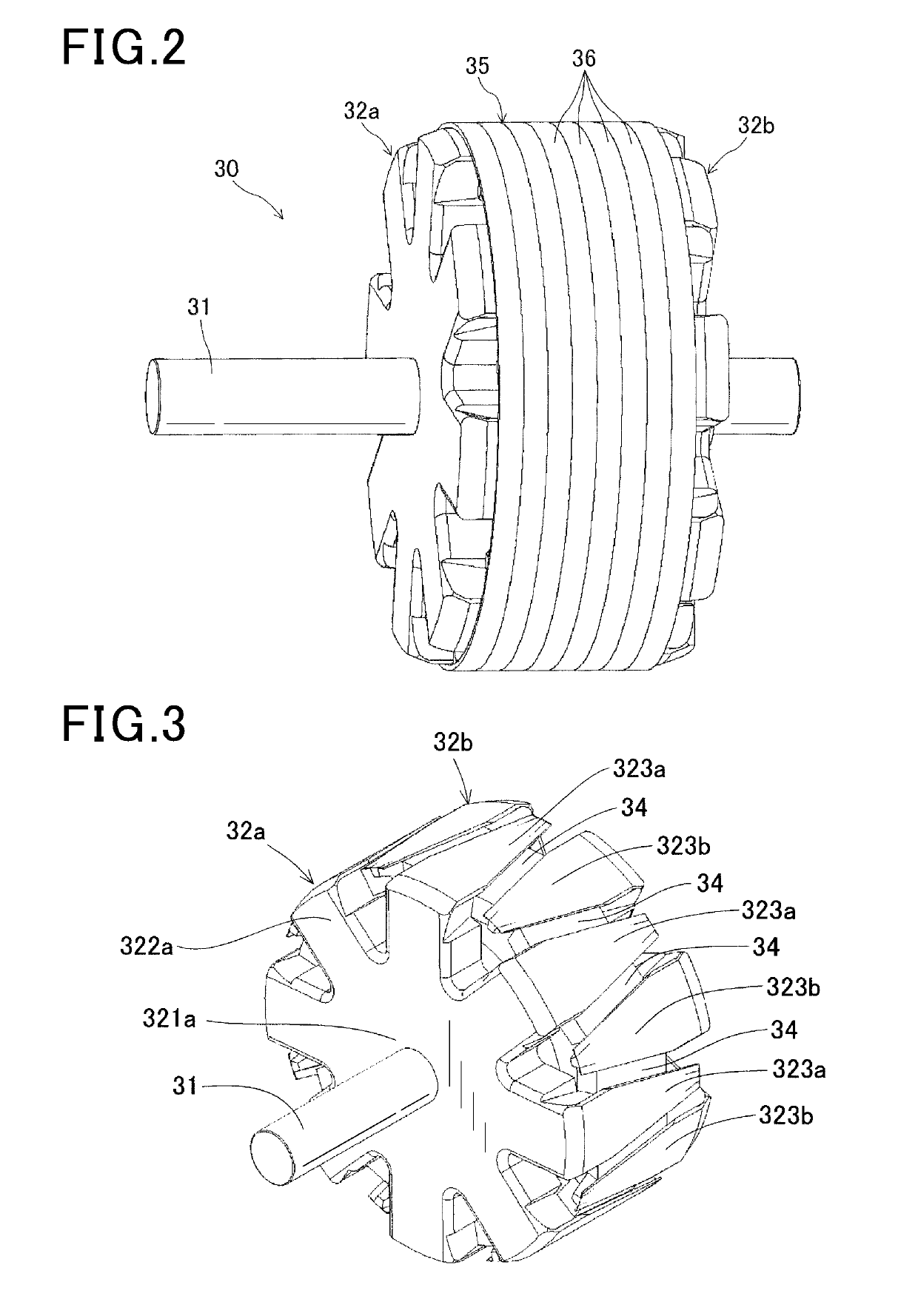
[0032]A rotor of a rotating electrical machine according to a first embodiment will be described with reference to FIGS. 1 to 12. The rotor of the first embodiment is, for example, installed in the rotating electrical machine used as a vehicle AC generator 1, and as illustrated in FIGS. 1 and 2, includes a housing 10, a stator 20, a rotor 30, a field winding power feeding mechanism, a rectifier 45, and the like.

[0033]The housing 10 includes a front housing 11 and a rear housing 12, each of the front housing 11 and the rear housing 12 being in a bottomed cylindrical shape opening at one end. The front housing 11 and the rear housing 12 are fastened with a bolt 13 with the openings being joined to each other. The stator 20 has a circular ring-shaped stator core 21 having not-shown multiple slots and teeth arranged in a circumferential direction, and an armature winding 25 having three phase windings wound around the slots of the stator core 21. The stator 20 is fixed to inner peripher...

second embodiment

[0057]A rotor 30 according to a second embodiment will be described with reference to FIGS. 13 to 18. A basic configuration of the rotor 30 according to the second embodiment is the same as that of the first embodiment, but the rotor 30 according to the second embodiment is different from that of the first embodiment only in a configuration of a tubular member 37. Hereinafter, differences and important points will be described. Note that the same reference numerals are used to represent elements common to those of the first embodiment, and detailed description thereof will be omitted.

[0058]The tubular member 37 of the second embodiment includes a steel wire 38 spirally wound to form a stack in an axial direction. The tubular member 37 is configured such that an inner diameter D3 (FIG. 14) in a steady state is smaller than the outer diameter D4 (FIG. 13) of claw-shaped magnetic pole portions 323. Note that the steady state in the second embodiment means a state in which no external f...


PUM


Abstract

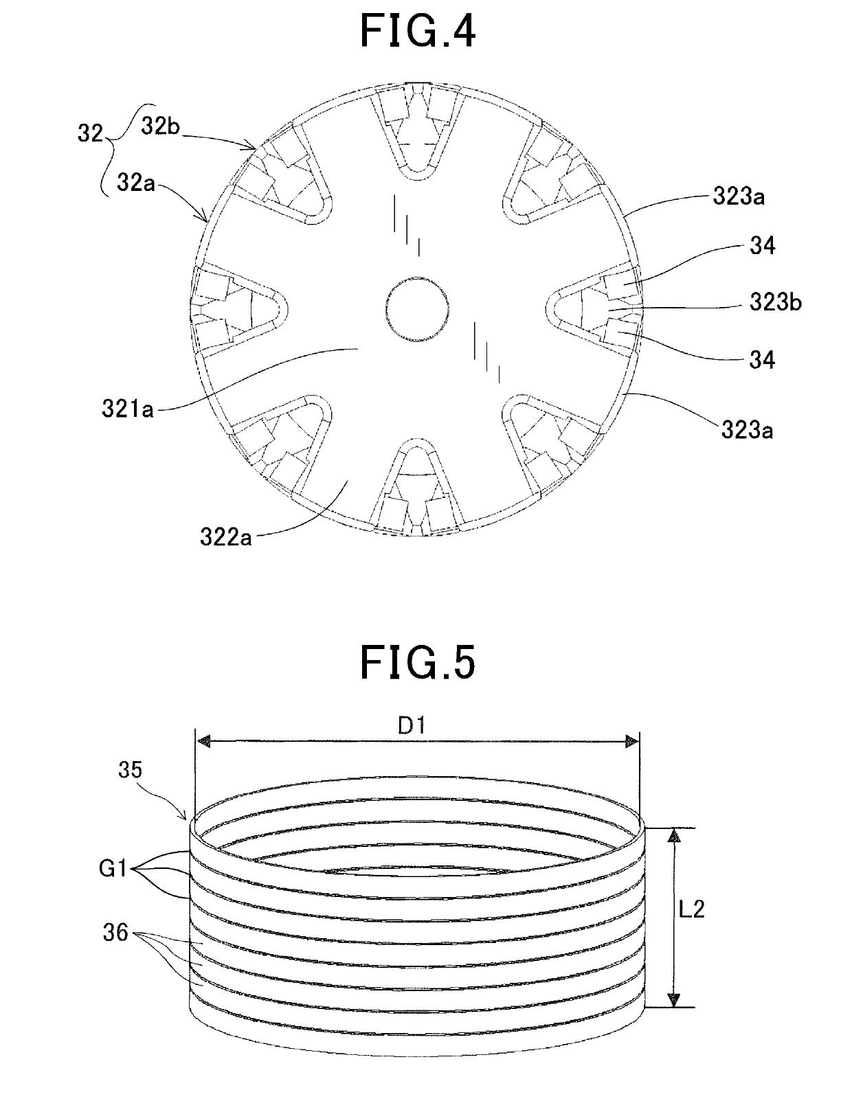
A rotor of a rotating electrical machine includes a field core having a boss portion, multiple disc portions, and multiple claw-shaped magnetic pole portions; a field winding wound around an outer peripheral side of the boss portion to generate magnetomotive force by power application; and a tubular member arranged so as to cover the outer periphery of the claw-shaped magnetic pole portions. The tubular member includes multiple steel plates stacked in an axial direction, and is configured such that an inner diameter in a steady state is smaller than the outer diameter of the claw-shaped magnetic pole portions.

Description

CROSS-REFERENCE TO RELATED APPLICATION[0001]The present application is based on and claims the benefit of priority from Japanese Patent Application No. 2016-112287, filed on Jun. 3, 2016, the entire description of which is incorporated herein by reference.TECHNICAL FIELD[0002]The present disclosure relates to a rotor of a rotating electrical machine that is installed in, for example, an automobile or a truck, and is used as an electrical motor or an electrical generator.BACKGROUND ART[0003]A rotating electrical machine including a stator, around which a stator winding is wound, and a rotor rotatably arranged in a state of facing the stator with an electromagnetic gap in a radial direction is known as a typical rotating electrical machine. A Lundell rotor including a field core having multiple claw-shaped magnetic pole portions and a field winding is known as a rotor of the rotating electrical machine. At the field core, a cylindrical boss portion fixed to a rotary shaft and magnetic...

Claims


Application Information

Patent Timeline
IPC IPC(8): H02K1/24H02K19/22H02K21/04H02K1/27
CPCH02K1/243H02K19/22H02K21/044H02K1/27H02K1/24H02K2213/03
Inventor TAKAHASHI, YUKIISHIZUKA, ATSUO
Owner DENSO CORP
Learn More