Flavor inhaler cartridge and flavor inhaler having flavor inhaler cartridge

a technology of flavor inhaler and flavor inhaler, which is applied in the field of flavor inhaler cartridge and flavor inhaler cartridge, can solve the problems of deterioration of material heat, variation in liquid atomization amount, etc., and achieve the effect of preventing local heat generation of porous heating elements

Inactive Publication Date: 2019-05-02
JAPAN TOBACCO INC
View PDF0 Cites 10 Cited by
  • Summary
  • Abstract
  • Description
  • Claims
  • Application Information

AI Technical Summary

Benefits of technology

[0020]With the flavor inhaler cartridge according to the present invention, by configuring a porous heating element which is a heating element used for suctioning and atomizing a liquid so as to have the specific resistance values described above, local heat generation of the porous heating element can be prevented.

Problems solved by technology

The occurrence of localized heat generation in the material as an element for suctioning and heating the liquid results in hastening deterioration of the material and impairing a function thereof and, at the same time, may cause a variation in atomization amounts of the liquid.

Method used


Image

  • Flavor inhaler cartridge and flavor inhaler having flavor inhaler cartridge
  • Flavor inhaler cartridge and flavor inhaler having flavor inhaler cartridge
  • Flavor inhaler cartridge and flavor inhaler having flavor inhaler cartridge

Examples


first embodiment

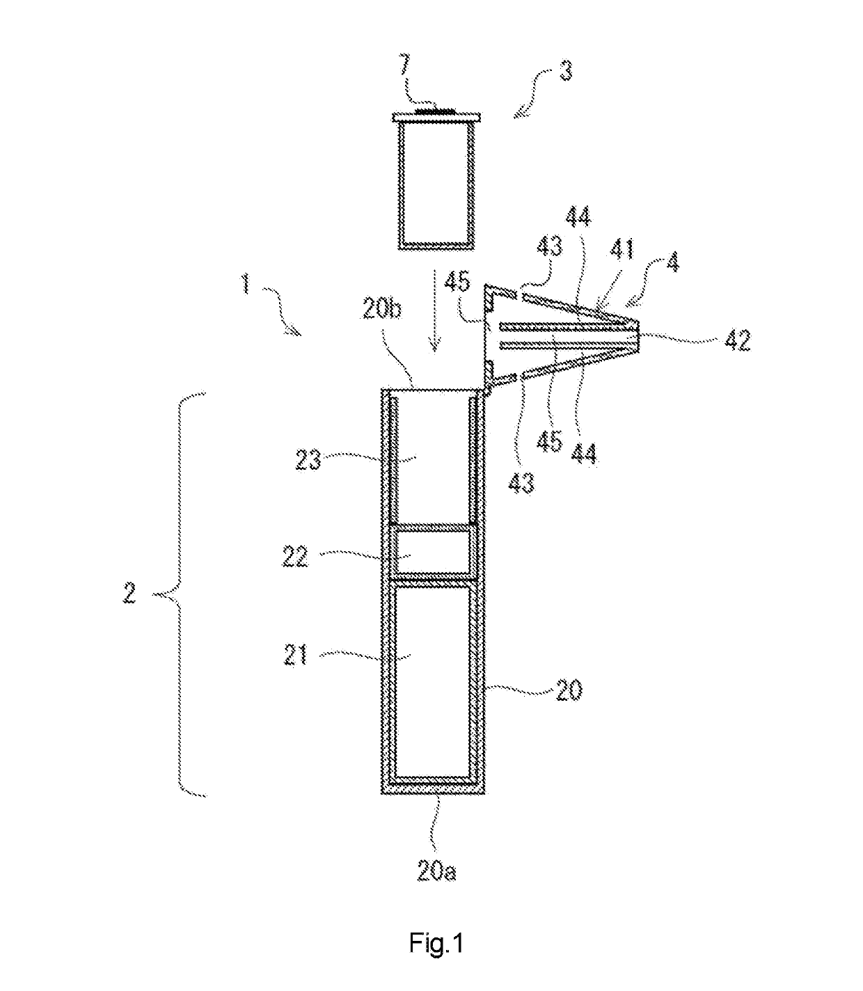
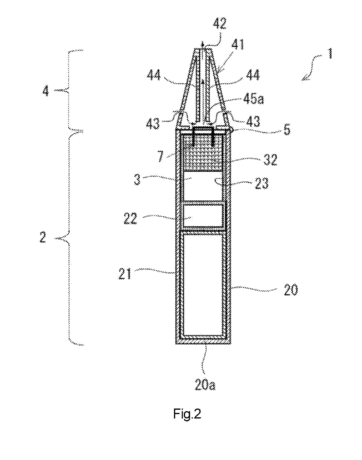
[0039]FIGS. 1 and 2 are schematic views of an electronic cigarette 1 as an example of an aerosol inhaler (a flavor inhaler) according to a first embodiment. The electronic cigarette 1 includes a main body portion 2 and a mouthpiece portion 4. The main body portion 2 has a main body-side housing 20 in which a battery 21, an electronic control portion 22, and the like are housed. The battery 21 may be a rechargeable battery such as a lithium-ion secondary battery.

[0040]The electronic control portion 22 is a computer which controls the entire electronic cigarette 1. The electronic control portion 22 may be a micro-controller which has a circuit board (not shown) mounted with a processor, a memory, and the like.

[0041]The main body-side housing 20 is, for example, a bottomed cylindrical shell, and the battery 21 and the electronic control portion 22 are arranged in this order from a side of a bottom surface 20a. In addition, a hollow housing cavity 23 for housing a cartridge 3 is formed ...

second embodiment

[0054]FIG. 5 is a diagram showing a cartridge 3A according to a second embodiment. In the cartridge 3A shown in FIG. 5, the liquid tank 31 (the liquid storage space 31d) is not provided with the liquid supplying member 32. In addition, a porous heating element 7A according to the second embodiment is configured such that the sucking portion 72 extends to a vicinity of a bottom portion of the liquid tank 31 and the sucking portion 72 directly sucks up the aerosol-forming liquid stored in the liquid storage space 31d.

third embodiment

[0055]FIG. 6 is a diagram showing a cartridge 3B according to a third embodiment. A porous heating element 7B in the cartridge 3B shown in FIG. 6 is solely constituted by the heater portion 71 and does not have the sucking portion 72. In the cartridge 3B, for example, the liquid supplying member 32 formed in a columnar shape is provided in the liquid tank 31, and the porous heating element 7B is placed on the upper surface of the liquid supplying member 32. The heater portion 71 in the porous heating element 7B shares a same structure as the heater portion 71 of the porous heating element 7 according to the first embodiment. The porous heating element 7B according to the present embodiment can suction and retain the aerosol-forming liquid from a rear surface of the heater portion 71 which is in contact with the upper surface of the liquid supplying member 32. It should be noted that the shape of the liquid supplying member 32 is not limited to the example described above.


PUM


Abstract

Provided is a flavor inhaler cartridge that comprises: a liquid storage part that stores an aerosol-generating liquid; and a porous heating body that is provided with a positive electrode and a negative electrode and that, when current has been passed between the positive electrode and the negative electrode, emits heat and thereby atomizes aerosol-generating liquid supplied from the liquid storage part. The relative standard deviation of the resistance value of the porous heating body as measured under prescribed experimental conditions is no more than 5.00.

Description

CROSS REFERENCE TO RELATED APPLICATIONS[0001]This application is a Continuation of PCT International Application No. PCT / JP2016 / 069012, filed on Jun. 27, 2016, all of which are hereby expressly incorporated by reference into the present application.BACKGROUND OF THE INVENTIONField of the Invention[0002]The present invention relates to a flavor inhaler cartridge and a flavor inhaler having the flavor inhaler cartridge.[0003]Flavor inhalers designed to enable a user to inhale an aerosol formed by vaporizing a liquid containing a flavor component and a fragrance using electrical energy are known.[0004]Japanese Patent No. 5612585 describes a planar composite as a heating element for performing atomization of a liquid stored in a flavor inhaler. Due to its structure, the planar composite described in Japanese Patent No. 5612585 also contributes to capillary transport of the liquid and is also used to suction the liquid. In addition, according to the invention described in Japanese Patent...

Claims


Application Information

Patent Timeline
Patent Type & Authority Applications(United States)
IPC IPC(8): A24F47/00A24F7/02A24B15/16H05B1/02H05B3/44A24F40/10A24F40/46A24F40/70
CPCA24F47/008A24F7/02A24B15/167H05B1/0297H05B3/44A24F47/00A61M15/06A24F40/10A24F40/44A24F40/70A24F40/46A61M11/042H05B3/12A61M2205/3653A61M2205/8206A61M2205/02H05B2203/021A24F40/42A24F40/485
Inventor NAKANO, TAKUMAMATSUMOTO, HIROFUMIYAMADA, MANABU
Owner JAPAN TOBACCO INC
Why Eureka
Try Eureka