System and method for valve activation

a valve activation and system technology, applied in the field of system and method of valve activation, can solve the problems of decreased cardiac output, inadequate perfusion of tissues throughout the body, shortness of breath, etc., and achieve the effect of improving the function of the valv

Active Publication Date: 2019-05-02
ABBOTT CARDIOVASCULAR
View PDF3 Cites 28 Cited by
  • Summary
  • Abstract
  • Description
  • Claims
  • Application Information

AI Technical Summary

Problems solved by technology

This can result in decreased cardiac output and inadequate perfusion of tissues throughout the body, with various resultant symptoms, including severe fatigue and shortness of breath.
Although the foregoing problems are identified in relation to the mitral valve, the same problems arise also in the tricuspid valve.
However, this system introduces problems in that the strength of the magnets is inherently non-linear, and may be too strong when they are close to each other, but too weak when spaced apart.
Thus, a set of magnets may become permanently attached to each other, with the result of blocking the blood flow.
However, such latter systems are complicated by the fact that they require open heart surgery for implantation, and are additionally complicated by the need to power an electrically operated system inside the heart.

Method used


Image

  • System and method for valve activation
  • System and method for valve activation
  • System and method for valve activation

Examples


Embodiment Construction

[0024]With reference to the figures, a description is provided of some embodiments having features of the invention. As used herein, the term “transcatheter” is used to describe a minimally invasive technique to enter the heart using a catheter via body lumens that give access to the heart, and may include penetrating a wall such as a septum with the catheter in a trans septal variation of the transcatheter procedure.

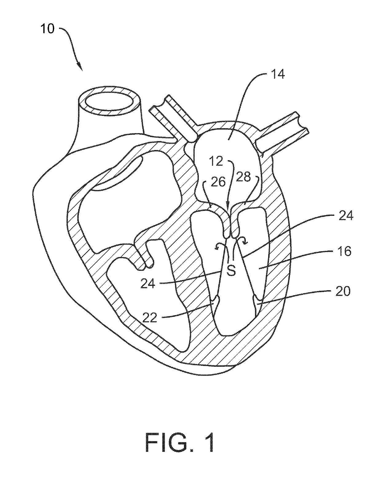
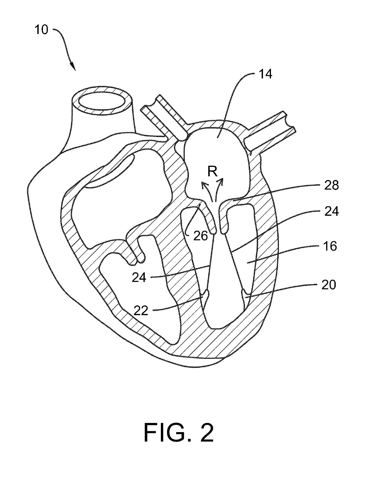
[0025]FIG. 1 and FIG. 2 have been described above. FIG. 1 shows a healthy heart valve in which coaptation of valve leaflets 26, 28 is achieved, and FIG. 2 shows an unhealthy heart valve in which leaflet coaption is not achieved so that regurgitation takes place as schematically indicated by arrows R.

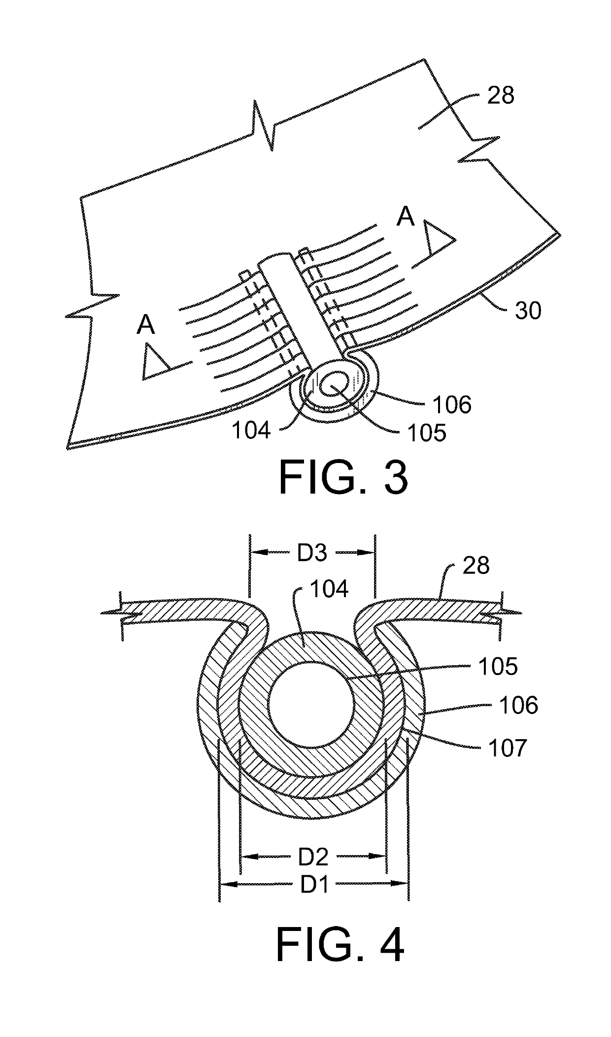
[0026]FIG. 3 shows an example of a system and method that accomplishes two objectives simultaneously. The first objective is to shorten the length of the free edge 30 of a leaflet 28 that fails to coapt with an opposing leaflet. The first objective is the subject of an appli...


PUM


Abstract

A method for improving the function of a valve in the heart of a patient, comprising attaching, to a leaflet of the valve, an element that is responsive to a magnetic field; positioning, outside of the heart of the patient, a coil connected to a source of electric energy; activating the source of electric energy to provide an oscillating current in the coil; and thereby providing an oscillating magnetic field through the coil to effect movement of the element and the leaflet.

Description

[0001]The present invention relates to systems and methods for correcting deficiencies that may arise in the operation of the human heart, specifically in the operation of valves in the human heart.[0002]An understanding of the human heart, and of deficiencies that may arise in the human heart, may be better understood with reference to the accompanying drawings, FIG. 1 and FIG. 2.[0003]FIG. 1 shows a sectional view of the heart 10 of a human subject. The mitral valve 12 is located between the left atrium 14 and left ventricle 16, generally adjacent to the aortic valve (not shown). The papillary muscles 20, 22 are finger-like muscular projections that extend from the wall of the left ventricle, as shown. Inelastic tendons, known as the chordae tendineae 24 extend from the antero-lateral papillary muscle 20 and from the postero-medial papillary muscle 22 to the anterior leaflet 26 and posterior leaflet 28 of the mitral valve 12, as shown. When connected at this level in relation to t...

Claims


Application Information

Patent Timeline
Patent Type & Authority Applications(United States)
IPC IPC(8): A61F2/24A61N2/02A61N2/00
CPCA61F2/2478A61N2/02A61N2/004A61F2/2463A61F2250/0001A61F2250/0029A61F2250/0014A61F2002/30291A61F2210/009A61F2230/0052
Inventor PRABHU, SANTOSHGREENBERG, JACOB L.KIZUKA, KOJI J.MARSOT, TRAVIS
Owner ABBOTT CARDIOVASCULAR
Why Eureka
Try Eureka